Hi Greierasul
We both failed I also forgot the output inductor.😀
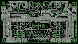
I put the output inductor and I become stable in ltspice with 0.5uH. This small value is easy to assemble and need small space in PCB.
regards
Ronaldo
We both failed I also forgot the output inductor.😀
I put the output inductor and I become stable in ltspice with 0.5uH. This small value is easy to assemble and need small space in PCB.
regards
Ronaldo
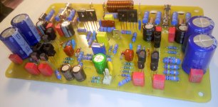
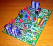
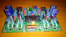
Stil missing parts...😱 Input capacitor, now changed ,to bipolar one , thermally coupled pairs on input transistors . 🙂
Regards,Alex
Regards,Alex
Attachments
-
 IMG_20161114_220817-001.jpg990.9 KB · Views: 1,395
 -
 IMG_20161114_220904-001.jpg841.5 KB · Views: 1,295
 -
 IMG_20161114_221027-001.jpg980.7 KB · Views: 1,190
 -
 IMG_20161114_220842-001.jpg850.9 KB · Views: 1,128
 -
 IMG_20161114_220850-001.jpg626.5 KB · Views: 1,018
 -
 IMG_20161114_220951-001.jpg835.1 KB · Views: 285
 -
 IMG_20161114_221006-001.jpg926.3 KB · Views: 395
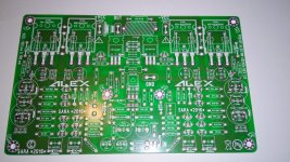
SARA 2016 v2 in progress ....🙂 just missing some parts as usual .....😉
Alex,
Where or how do you make your prototypes?
Carlos
Hi,CarlosAlex,
Where or how do you make your prototypes?
Carlos
Hand made at home ....🙂
Regards,Alex
Alex two bipolar electrolytic capacitors in series... 🙂 You do envious and Cyril Bateman himself 🙂
Personally made by the master himself ! Looking good Alex!
Thank you 🙂
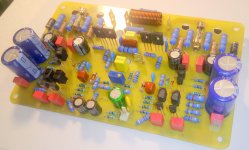
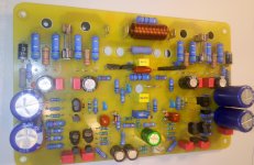
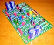
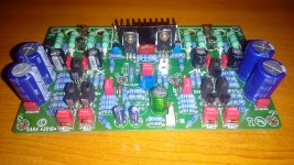
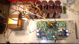
Finally I got the last components .....😉
Regards,Alex
Attachments

SARA 2016 - tested
Happy new year ! to all .
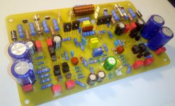
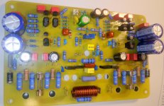
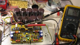
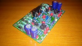
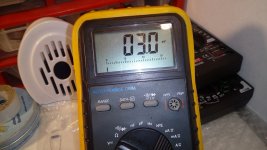
Good news 😀 ,I have tested SARA 2016 with success ,it's a live and playing well.
Power rail supply only for testing +/-35V , load 6 ohms , offset 10 to 12 mV .
Ton correction, not used ,at all in this case . Short movie with amplifier in use ..... https://www.youtube.com/watch?v=KG_K_8rEDu0 😉
Regards ,Alex
Happy new year ! to all .
Good news 😀 ,I have tested SARA 2016 with success ,it's a live and playing well.
Power rail supply only for testing +/-35V , load 6 ohms , offset 10 to 12 mV .
Ton correction, not used ,at all in this case . Short movie with amplifier in use ..... https://www.youtube.com/watch?v=KG_K_8rEDu0 😉
Regards ,Alex
Attachments


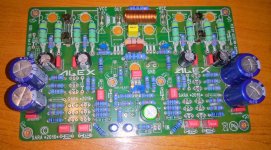

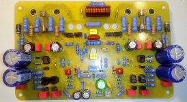
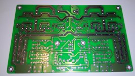
Finished ,populating boards with components 🙂 will test soon 😉
Regards,Alex
Regards,Alex
Attachments


Great amp.
If it only half that good as simulation, is still great.
In my opinion CCS-s (Q1, Q2, Q13, Q20) are too complicated. They are effectively bypassed by R40 and R41. You can replace them (CCS) by resistors, like in Leach Amp, and performance would not be affected too much.
If it only half that good as simulation, is still great.
In my opinion CCS-s (Q1, Q2, Q13, Q20) are too complicated. They are effectively bypassed by R40 and R41. You can replace them (CCS) by resistors, like in Leach Amp, and performance would not be affected too much.
Great amp.
If it only half that good as simulation, is still great.
In my opinion CCS-s (Q1, Q2, Q13, Q20) are too complicated. They are effectively bypassed by R40 and R41. You can replace them (CCS) by resistors, like in Leach Amp, and performance would not be affected too much.
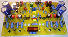
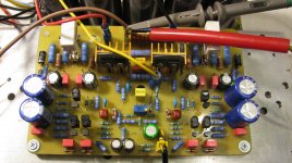
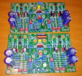
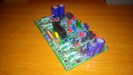
I'm only builder of the amplifier 🙂 Tested also SARA 2016 v.1 and work very well , offset only 3mV 😀 Some pictures ..... 😀
Regards,Alex
Attachments
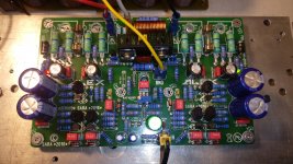
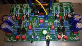
Nice work!I'm only builder of the amplifier 🙂 Tested also SARA 2016 v.1 and work very well , offset only 3mV 😀 Some pictures ..... 😀
Regards,Alex
Is it any reason you are using metal oxide 1W resistors?
Last edited:
Nice work!
Is it any reason you are using metal oxide 1W resistors?
Thanks, reason was only quantity limit of order , for 0.6 watts minimum was 100 pieces ,and for 1W was only 20 pieces .😉
Regards,Alex
Great amp.
If it only half that good as simulation, is still great.
In my opinion CCS-s (Q1, Q2, Q13, Q20) are too complicated. They are effectively bypassed by R40 and R41. You can replace them (CCS) by resistors, like in Leach Amp, and performance would not be affected too much.
Yes, you could replace the CCS's with resistors, no problem, but you will lose most of the "constant" of the current from the input stage. For better work, R40 and R41 could be replaces with CRD diodes. In fact, initially, in SARA-2012, there was again another CCS's in that places but I removed them because the schematic was too complex. The CRD's could be the most right parts there. Simple and effective.
The cascode of the CCS ensure a very high impedance and a great input stage immunity against noise of the rails.
Oh,where you buy?Thanks, reason was only quantity limit of order , for 0.6 watts minimum was 100 pieces ,and for 1W was only 20 pieces .😉
Regards,Alex
Yes, you could replace the CCS's with resistors, no problem, but you will lose most of the "constant" of the current from the input stage. For better work, R40 and R41 could be replaces with CRD diodes. In fact, initially, in SARA-2012, there was again another CCS's in that places but I removed them because the schematic was too complex. The CRD's could be the most right parts there. Simple and effective.
The cascode of the CCS ensure a very high impedance and a great input stage immunity against noise of the rails.
Currents provided to diff pairs are already non-constant, because they vary with input signal, due to R40/R41. R40/R41 also makes PSRR worse.
What i wanted to say is that simple CCS with one transistor and Zener is enough. All what You get from cascoding is swamped in R40/41.
CCRD are good idea, but little too expensive (just quick look at mouser.com, maybe You have better/cheaper source).
- Home
- Amplifiers
- Solid State
- SARA-2016