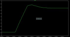
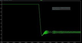
Your modification is not feasible for real world unfortunately...Amplifier may oscillate and even make that at the high frecquency. I attached two charts with step response. One for the ideal case and one for the realistic case. Maybe will work at the first glance, but the oscillations may saturate the input stage. Probably the heat will be much greater at the heatsinks. In conclusion is a risky business.
Attachments
a little difference in simulation
Thanks for your comment.
I get a little different result in my simulations. I test different voltages levels with equivalent results. So, I suppose it is models differences.
Of course there is a sign of oscillations, but it is not so bad in my simulation.
I suppose it can be repaired adjusting the R - C time constant in Q20 and Q21 to optimum value as it is tipical output stage oscillation
What do you think?
Regards
Ronaldo
Attachments
Last edited:
In the reality, over the R56 it is a parasitic capacitance of 2pF, maybe more. Simulates again with this value or bigger.
Yes, if I add 2pF in parallel with R56 the thing become terrible.😱
But if I increase C17 and C18 all become as I show before. I dont believe we can find more than 4.7pF as parasitic capacitance around R56 and we can also minimize it in layout. 🙄
Well as told before, i suppose it is project compromise. It become interesting if we can get specs improvement.
But if I increase C17 and C18 all become as I show before. I dont believe we can find more than 4.7pF as parasitic capacitance around R56 and we can also minimize it in layout. 🙄
Well as told before, i suppose it is project compromise. It become interesting if we can get specs improvement.
what is your suggestion of compensation for this circuit Hpavictor?
The actual compensation circuit was chosen to achieve the lowest possible distortion.
I also changed the VAS stage with this intention.
thanks
Ronaldo
The actual compensation circuit was chosen to achieve the lowest possible distortion.
I also changed the VAS stage with this intention.
thanks
Ronaldo
Last edited:
R_merola , with signal step and capacitiv load over the 8ohm resistive load, your version oscillate for 1nF and bigger. My version without tunning, accept up to 100nF without output coil. In the real life , the loudspeakers are a complex load and there are a lot of them which has a 1uF. In my opinion, first of all, the amplifiers must to be very stable in the various conditions, with various speakers. Again, in my opinion, the THD distortions under the 0,010% in 20hz-20khz band, will not be audible, but a poor clipping yes. In your version, the clipping at 20khz has a tendency to stick to the rails.
SARA-2016 performs very well in the THD domains, very close to the famous commercial amplifiers, and in the same time keeps a simple schematic. The scheme wich can be debugged, repaired by any electronics man, all over the world.
For special applications, I have a commercial schematic (non-free), quite stable, which has a excellent THD performances (see in the pictures), but for home audio it's not necessary.
Attachments
Thank you for your points and comments.
You give me more information about troubleshooting amplifier in simulations.
I still work in this modification with more time as we are in weekend now.
If you do not mind I would like to share my results in your thread and read your comments.
By the way, I wonder to have a look in your advanced projects. If possible send me a PM with more details.
Regards
Ronaldo
If you want a better THD without any cost, remove R45 and R47 and you will have more open loop gain. I used them for a smaller and linear damping factor for all the frequencies of the audio band. Honestly I think a THD better than 0,001% it is not very simple to obtain in the real world.The parasitic components and a stray fields are a hard to be ignored.
Last edited:
It happens in the original SARA
greierasul,
After lots of tests I become confused.😕
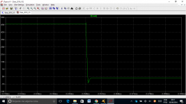
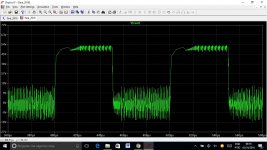
I did lots of tests in my circuit modification. When I have a good behavior the distortion is high. When I got low distortion When I put capacitive load in parallel with the load I got instability.
I decided to test the original circuit with 100nF in parallel with load(your circuit with my models - Cordell based models).
Attached you can find the result!
I also tested lots of circuits and is a bit hard to find stable circuits with 2uF capacitive load. It happens even in commercial products. Here in the forum, lots of popular projects become unstable with load, so some project engineer do not recognize this test.
I have some that have low distortion and is stable with 2uF in the output. It is not so hard to achieve in simple circuit, when it is well done.
Please make your comments.
Thnx
Ronaldo
greierasul,
After lots of tests I become confused.😕
I did lots of tests in my circuit modification. When I have a good behavior the distortion is high. When I got low distortion When I put capacitive load in parallel with the load I got instability.
I decided to test the original circuit with 100nF in parallel with load(your circuit with my models - Cordell based models).
Attached you can find the result!
I also tested lots of circuits and is a bit hard to find stable circuits with 2uF capacitive load. It happens even in commercial products. Here in the forum, lots of popular projects become unstable with load, so some project engineer do not recognize this test.
I have some that have low distortion and is stable with 2uF in the output. It is not so hard to achieve in simple circuit, when it is well done.
Please make your comments.
Thnx
Ronaldo
Attachments
Last edited:
Put the library here because the results are different between us. Anyway, the idea it is to have first time a stable schematic for a large variety of loads.
Hi,
Nice project and a very well designed PCB, the routing is superb! May I ask what schematic/pcb software are you using?
Christian
Nice project and a very well designed PCB, the routing is superb! May I ask what schematic/pcb software are you using?
Christian
New project based on SARA
greierasul
I dont believe we have spice library problem. Anyway I attached a file with all libraries I applied in this test. Like I wrote you they are Bob Cordell based libraries except the LED, Zener and BAV21 library.
Other are mainly component factory libraries and I use to test then before use.
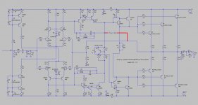
I create a new SARA version which is really a new project. I was based in the gain-bandwidth product as described in “Introduction to Electroacoustics and Audio Amplifier Design” from W. Marshall Leach, Jr. - Second Edition. After basic definition based on this theory, I used LTSpice to get the best performance in all tests done.
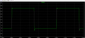
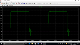
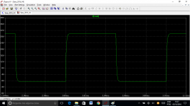
The final result is stable with 2.2uF in parallel with 8R loads and with a 3 way speaker box. It is in ASC file to other ´person also test and generate new points and improvements.
Please, have a look in frequency response. It is flat to near 100KHz and drop slowly until 10MHz in 5 dB range.
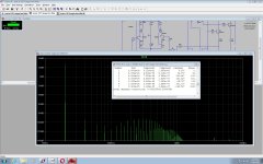
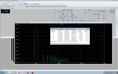
The distortion now is near to 0.0014%. It is a good number as we use only easily available small transistors with no special specification in signal gain stage of this project.
Regards
Ronaldo
greierasul
I dont believe we have spice library problem. Anyway I attached a file with all libraries I applied in this test. Like I wrote you they are Bob Cordell based libraries except the LED, Zener and BAV21 library.
Other are mainly component factory libraries and I use to test then before use.
I create a new SARA version which is really a new project. I was based in the gain-bandwidth product as described in “Introduction to Electroacoustics and Audio Amplifier Design” from W. Marshall Leach, Jr. - Second Edition. After basic definition based on this theory, I used LTSpice to get the best performance in all tests done.
The final result is stable with 2.2uF in parallel with 8R loads and with a 3 way speaker box. It is in ASC file to other ´person also test and generate new points and improvements.
Please, have a look in frequency response. It is flat to near 100KHz and drop slowly until 10MHz in 5 dB range.
The distortion now is near to 0.0014%. It is a good number as we use only easily available small transistors with no special specification in signal gain stage of this project.
Regards
Ronaldo
Attachments
-
 SARA_2016_V4_SQUARE_8R+2.2UF.png39.7 KB · Views: 191
 -
 SARA_2016_V4_SQUARE_8R.png40.1 KB · Views: 180
 -
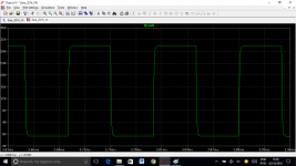 SARA_2016_V4_SQUARE_3WAY_SPEAKER_BOX_MODEL.png45.3 KB · Views: 1,150
 -
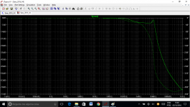 SARA_2016_V4_Freq_Resp.png74.6 KB · Views: 1,174
 -
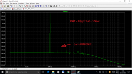 SARA_2016_V4_FFT-8R+2.2uF.png60 KB · Views: 1,195
 -
 SARA_2016_V4_FFT-8R.png44.8 KB · Views: 1,227
 -
SARA_2016.txt4.6 KB · Views: 237
-
Sara_2016_V4.ASC24.5 KB · Views: 203
Last edited:
Very interesting Ronaldo. I'll looking in detail at your version next week because I must to go in Berlin for a few days. Please, if you can, put the schematic in a jpeg format. There I have only the phone and I do not have LTSpice. Best regards, Raimond.
greierasul
I tryed, but the image is not readable. Sorry
I can wait until you came back from Berlin. So, there is more time to my and others tests.
Ronaldo
I tryed, but the image is not readable. Sorry
I can wait until you came back from Berlin. So, there is more time to my and others tests.
Ronaldo
Sara 2016
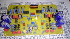
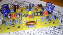
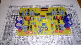
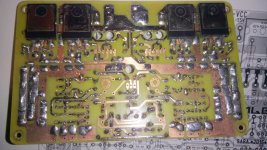
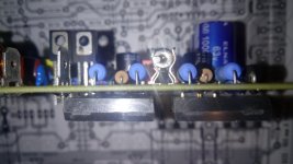
SARA 2016 v2 in progress ....🙂 just missing some parts as usual .....😉
Regards, Alex
SARA 2016 v2 in progress ....🙂 just missing some parts as usual .....😉
Regards, Alex
Attachments
-
 IMG_20161113_162356.jpg1 MB · Views: 855
 -
 IMG_20161113_162441.jpg1,019 KB · Views: 853
 -
 IMG_20161113_162415.jpg1 MB · Views: 540
 -
 IMG_20161113_162348.jpg1.1 MB · Views: 543
 -
 IMG_20161113_162502.jpg1.1 MB · Views: 750
 -
 IMG_20161113_193452.jpg753.2 KB · Views: 761
 -
schematic SARA-2016 v2.pdf64.8 KB · Views: 703
Hi Alex
I just propose you use BAV21 instead of 1N4148 in D7 and D8 position as the first one can handle well the VAS voltage swing.
I also aply 2N5551 in position Q23, Q12 and Q30I just update my simulation file and I got the instability behavior as before. Following Mr Greierasul this project is instable, so could you share oscilograms as become avaliable.
By the way, very nice PCB as usual.
Kindest Regards
Ronaldo
Yes, BAV20 , BAV21 are a better choice but are the rarely too on the market, harder to find it. The project isn't instable, it is very stable, but with capacitive load it is necessary an output coil, like in the schematic. For your confusion I'm to blame. In the simulations, I was rushed and I forgot base resistors at the 25ohm's values. Because of this reason I was wrong. Sorry again.
- Home
- Amplifiers
- Solid State
- SARA-2016