For offline analytical purposes the captured file could be processed as a 192K file and rescale the frequency numbers (divide by 4). Sometimes I get this even when i don't intend for it with the windows sound engine.
DavidA is playing with some FFT/DFT stuff and may be able to make a basic analysis from his work that would be capable for 768KHz.
DavidA is playing with some FFT/DFT stuff and may be able to make a basic analysis from his work that would be capable for 768KHz.
You are right Jcx,
but there is no real time analysis in that case such as using audio analyzer like Arta
is much more straightforward than recording data and making post treatment.
Anyway, that could be complementary and could be possible if i can implement
the USB3 Ftdi bridge as i speak earlier.
mroether,
Good news, anyway it is alone(?) and it's not really a free SW.
My target on the global design is to offer the higher performance possible, high
flexibility with lot of features but with a DIY price (if possible).
Demian,
Not sure to understand what you explain.
Do you mean recording locally (on the ADC system) the data at high sample rate
(for a specified time), and then send it as 192kHz file to the computer ?
(can be done but we lost again real time).
Frex
I was thinking offline analysis which is less useful. But on moe than one occasion software did not notice that the actual rate was much different from the reported rate. Some software may just work even though it thinks its looking at 192 and 768 is being fed to it. I don't think there is a reason for the software to do a check on the actual sample rate.
Hello,
Ok, i understand Demian. You say that even if the software run at a specified sampling rate,
that doesn't care as long as the stream itself work at its own sampling frequency.
We just need apply ourself the right multiplier of frequency reading.
Ok, but this still require the need to work with a link that can be able to work at high sampling rate.
An this is that i pointed out mainly.
I thinking that using an easy to do 24/192k interface (cheap) coupled with a digital frequency shift
selection to explore all the available spectrum would be smart and would decrease the overall cost
while offering a versatile analysis features.
For off-line measurements with full bandwidth data, then the high speed USB3 link to record
the raw data would do the job.
I think both are very complementary (i need really often to see what i measure in real time)
and the USB3 link could be seen as an optional module in the final design.
I work on both.
Frex
BTW the CoolEdit/Audacity SDK does have a small prime factor FFT (so 48/96k FFT's are OK) and one could write some fairly nice scientific research tools on top of its memory management and user interface, I know Angelo Farina sells some very interesting plugins.
Sorry for the semi OT, but do you or any others involved here have any links to plug in for Cooledit pro2.1?
I've become used to the software but I have yet to apply additional DSP or vsti plug in.
Specifically I would love to be able to analyse audio spectra for thd noise
(This comes after using a software spectrum analyser written in VB to measure amplifier THD+N. It wasn't optimal as the code is really designed for measuring mains frequency harmonic distortion amplifiers and is limited in bandwidth for F0-F99 so I have only been able to measure THD with input frequency of 50 Hz rather than the standard 1kHz)
Hello,
Ok, i understand Demian. You say that even if the software run at a specified sampling rate,
that doesn't care as long as the stream itself work at its own sampling frequency.
We just need apply ourself the right multiplier of frequency reading.
Ok, but this still require the need to work with a link that can be able to work at high sampling rate.
An this is that i pointed out mainly.
I thinking that using an easy to do 24/192k interface (cheap) coupled with a digital frequency shift
selection to explore all the available spectrum would be smart and would decrease the overall cost
while offering a versatile analysis features.
For off-line measurements with full bandwidth data, then the high speed USB3 link to record
the raw data would do the job.
I think both are very complementary (i need really often to see what i measure in real time)
and the USB3 link could be seen as an optional module in the final design.
I work on both.
Frex
For this much effort, I would think you can get an XMOS IC integrated which will give you 768k without any compromises.
Hello Chris,
I must say that writing the needed code for the XMOS is not in my skill.
I think (but i'm maybe wrong) that using it with all I/O and with ASIO to reach the max
sampling rate will need to get a proprietary license.
I have share some message with Hp, and he has already be able to receive
1536kHz sampling rate with a Xmos board (USBstreamer).
His analysis software (HpW) is capable to concatenate the 4 channels@192k
to one and show the real 1536kHz bandwidth.
Maybe i can ask him more about that..
Frex
Hi Frex,
As far as I know, the was the muliple 192KHz channels idea one that JensH came up with when he was working with the USBStreamer from miniDSP. You just have to split the data stream from the ADC into multiple I2S streams and feed them to a device, such as the USBStreamer. The rest of the data path will unchanged and it's a matter of analyzer software to put the stream back together. And I believe that's what HpWs software supports.
Mogens
The rest of the data path will unchanged and it's a matter of analyzer software to put the stream back together. And I believe that's what HpWs software supports.
Mogens
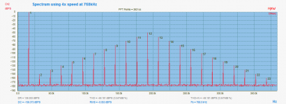
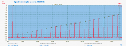
Exactly,
Supporting 24 Bit (as USBStreamer allows):
- Stereo 2X Speed (2 * 192kHz = Final SR = 384kHz)
- Stereo 4X Speed (4 * 192kHz = Final SR = 768kHz)
- Mono 8X Speed (8 * 192kHz = Final SR 1536 kHz)
on Input and/or Output using 100% bit perfect ASIO interface 😀
See pictures...😀
Hp
Attachments
Hi, I found this site recently.This is the very concern thing I want to know.I made ADC to digitalize a record one years ago.
I prefer SAR to delta-sigma because I couldn't get good result from pcm4202 before and my DAC use multibit DAC chips.I chose AD7982. This is the PCB.It works well for digitizing.

This is analog signal and analysis of captured digital data when input
is -90dBFS sine.

This is -100dBFS sine.

This is -90dBFS square wave.

These measurement is done in 768k/sample. Sampled data is filtered by FPGA and downsampled to 96k/sample with 22kHz band limit like CD.Processed data sends to PC via SPDIF or writes into SDmicro(fat32).
T.H.D.+N of AD7982 is -111dbFS(almost 18bit). High sampling rate(768k)can improve S/N.If in 768k/sample,S/N is around 100dB as is specsheet data.
Now I want to improve S/N of my ADC to 120dB(20bit) which is enough for measurement. AD7982 is a little bit noisy for that purpose,though it is enough for a record.LTC2380-24,which I couldn't find at the time I designed the PCB, is very interesting part.
I think it's passible to get 20bit resolution. Thank you for the information.🙂
I prefer SAR to delta-sigma because I couldn't get good result from pcm4202 before and my DAC use multibit DAC chips.I chose AD7982. This is the PCB.It works well for digitizing.
This is analog signal and analysis of captured digital data when input
is -90dBFS sine.
This is -100dBFS sine.
This is -90dBFS square wave.
These measurement is done in 768k/sample. Sampled data is filtered by FPGA and downsampled to 96k/sample with 22kHz band limit like CD.Processed data sends to PC via SPDIF or writes into SDmicro(fat32).
T.H.D.+N of AD7982 is -111dbFS(almost 18bit). High sampling rate(768k)can improve S/N.If in 768k/sample,S/N is around 100dB as is specsheet data.
Now I want to improve S/N of my ADC to 120dB(20bit) which is enough for measurement. AD7982 is a little bit noisy for that purpose,though it is enough for a record.LTC2380-24,which I couldn't find at the time I designed the PCB, is very interesting part.
I think it's passible to get 20bit resolution. Thank you for the information.🙂
Hi, I found this site recently.This is the very concern thing I want to know.I made ADC to digitalize a record one years ago.
I prefer SAR to delta-sigma because I couldn't get good result from pcm4202 before and my DAC use multibit DAC chips.I chose AD7982. This is the PCB.It works well for digitizing.
Very nice. How did you solder the Artix 7? Did you use a reflow oven, or hot air/IR?
Very nice. How did you solder the Artix 7? Did you use a reflow oven, or hot air/IR?
BGA is annoyance for self-making. I usually don't use this type of package because I can't solder by myself.I had no choice about this PCB to use BGA because I need somewhat large memory(512kbytes).
There is a PCB manufactures who arrange assembly including BGA soldering.It needs metalmask whose cost is almost same as PCB.In this case,both are probably US$450(PCB cost include 5pcs PCB,metalmask cost includes 4pcs BGA soldering fee).
If PCB doesn't have BGA,total cost is half.BGA is annoyance indeed.😕
One merit of BGA is reliability.BGA soldering is ckecked with X-ray.QFP soldered by myself sometimes has contact failurs.I don't know the merit is worthy of cost.
News...
Hello,
xx3stksm , you have also made a good job !
Your screen-shoots seem to show analysis software, does it is from you (for your board)
or is that a commercial one ? It looks pretty well.
Now, some news of the project.
After receiving the SDRwidget bare PCB, I populated the board and uploaded the firmware
on it without major issue. Anyway, that require some reading that take some time.
To test the USB/I2S link that provide the USBwidget board, i used a small CPLD board
that emulate the I2S like an ADC and provide also the master clock.
The data sent by this board is a 48points sine lockup-table with selectable amplitude of -1dBFS or -80dBFS.
And, the SDR widget works really well !
I used it on Ubuntu at any sampling rate without any driver (plug and play ).
I run it with jaaa FFT software in full duplex mode at 192kHz successfully.
On windows (win7-64), in UAC1 mode all win applications recognize it at 48k/24bits.
When ASIO drivers are installed on windows, 96/192kHz operation are possible
but the application must be able to use ASIO.
I tried Arta and REW 5.1 and both work with ASIO at any sampling rate.
So, I am very enthusiast with it !
You can show below a small picture of the test setup (SDR board and CPLD test) :

Of course, the next step now is to connect the SDR widget to my ADC for replacing
the SPDIF link and the PCI sound card.
Compared to any others solution (like XMOS), for up to 192k operation
the SDRwidget is very interesting solution, with overall price much lower
and the open sourced project is very DIY friendly ! (much infos about it on Google).
Regards.
Frex
(Note that i have some SDRwidget bare PCB available, if you need to get one, go HERE.)
Hello,
xx3stksm , you have also made a good job !
Your screen-shoots seem to show analysis software, does it is from you (for your board)
or is that a commercial one ? It looks pretty well.
Now, some news of the project.
After receiving the SDRwidget bare PCB, I populated the board and uploaded the firmware
on it without major issue. Anyway, that require some reading that take some time.
To test the USB/I2S link that provide the USBwidget board, i used a small CPLD board
that emulate the I2S like an ADC and provide also the master clock.
The data sent by this board is a 48points sine lockup-table with selectable amplitude of -1dBFS or -80dBFS.
And, the SDR widget works really well !
I used it on Ubuntu at any sampling rate without any driver (plug and play ).
I run it with jaaa FFT software in full duplex mode at 192kHz successfully.
On windows (win7-64), in UAC1 mode all win applications recognize it at 48k/24bits.
When ASIO drivers are installed on windows, 96/192kHz operation are possible
but the application must be able to use ASIO.
I tried Arta and REW 5.1 and both work with ASIO at any sampling rate.
So, I am very enthusiast with it !
You can show below a small picture of the test setup (SDR board and CPLD test) :
Of course, the next step now is to connect the SDR widget to my ADC for replacing
the SPDIF link and the PCI sound card.
Compared to any others solution (like XMOS), for up to 192k operation
the SDRwidget is very interesting solution, with overall price much lower
and the open sourced project is very DIY friendly ! (much infos about it on Google).
Regards.
Frex
(Note that i have some SDRwidget bare PCB available, if you need to get one, go HERE.)
The latest Win 10 creators update is supposed to have native UAC 2 drivers and may work without ASIO (or a hacked Thesycon driver) like Linux.
Sent from my LG-H811 using Tapatalk
Sent from my LG-H811 using Tapatalk
Hello,
xx3stksm , you have also made a good job !
Your screen-shoots seem to show analysis software, does it is from you (for your board)
or is that a commercial one ? It looks pretty well.
I use RX4(iZotope) for audio analysis.It is mainly for editting audio signal to controll declic,denoise,equalizer and sampling conversion.I used this for the first time to degitalizing of my records.Then I found this was also good tool for analysis.
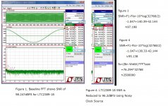
By the way I read your measurement data at #56.You got -115.1dBFS noise level at 48kHz/s.That's great.My ADC board as I posted at #130 was -111.2dB.This was sampled at 768kHz.If it was sampled like you(1.5MHz),it can gain 3dB,total noise floor -114.2dB.
I think this doesn't depend on a chip used.Your data is almost close to physical limit.My board still has some problems.After fixing them,mine probably becomes close to you.My goal is -120dB.From your data and another consideration,the key to reach -120dB is high sampling rate(6MHz)and carefull board layout.I think it's possible.🙂
Thank you for the tip Demian.
I read a little and that seem only work for playback, at least for now.
Anyway, i try to update my win10 to latest creator update to try this, i'm curious...
Hello xx3stksm,
Too bad that izotope price list is so high, that seem a good tool.
What do you use as processing in the FPGA ? Decimating FIR as me ?
Note that i don't know what clock you have used, but low phase noise and short path
is essential to meet the full ADC specs.
Regards.
Frex
What do you use as processing in the FPGA ? Decimating FIR as me ?
Note that i don't know what clock you have used, but low phase noise and short path
is essential to meet the full ADC specs.
Regards.
Frex
The processing in FPGA is plain FIR(40kHz cutoff,1024 order). It has sharp cutoff to eliminate spectrums which have potential chance to be aliasing noise.

High sample rate SARs like LTC2380 have internal clock for its conversion. External clock into the chip acts only for shift clock of sampled data acording to datasheet.
I think stable power and analog signal layout are more important than external clock.
Hello xx3stksm,
The internal clock of the ADC is only for the SAR process, it's not the ADC sampling clock.
The SNR of any ADC can be limited by the jitter of sampling clock.
Designers take care about this with high-speed ADC, but but even for lowest speed high resolution ADC
a poor jitter can result in lower SNR.
Of course as you say, a very good multi-layers layout is essential to get the full performance of the ADC.
But also proper grounding (no loop) and low noise power supply are also required.
Regards.
Frex
Hello xx3stksm,
The internal clock of the ADC is only for the SAR process, it's not the ADC sampling clock.
The SNR of any ADC can be limited by the jitter of sampling clock.
Designers take care about this with high-speed ADC, but but even for lowest speed high resolution ADC
a poor jitter can result in lower SNR.
Of course as you say, a very good multi-layers layout is essential to get the full performance of the ADC.
But also proper grounding (no loop) and low noise power supply are also required.
Regards.
Frex
Hello Frex. I agree with you.What I wanted to emphasize is that CNV is real sampling clock and SCK is only shift clock of sampling data in many SAR ADCs like this.I need to take good care about jitter of CNV.

BTW.I'm now considering to redesign my ADC board to be capable of measurement use which require much accuracy than recording one.I have almost finished fixing up problems on the ADC board. One concerning thing is jitter of clock,as you say it's important factor for high resolution ADC.
I have measured noise power which may come from jitter of ADC clock.But measured rezults is not what I expected.I thought I can find out some imfluence caused by jitter.I fail to find increase of noise power so far.
One reason for this is probably my measurement circumstance.Test signal for ADC comes from my self-made multibit DACs(pcm1704 and LTC2642) which doesn't have low THD+N for good measurement.They are almost -100dBc which mean less than -100dBc is vague.But above -100dBc level,I can't find footprint of jitter in spite of dirty clock.
This is good explanation about jitter.
Solutions - A Low Jitter Clock is Required to Evaluate High Resolution ADCs Please see attached.
I calculate jitter of Fig 1 with clean clock and Fig 4 with dirty clock.I think the calculation is probably correct and proves clock jitter decreae SNR.But that is against my measurement.Why can't I find decresed SNR ?
Is there different bandwidth between Liner-Tech simulations and my measurement ? Liner-Tech is 1.25MHz while mine is usually 20kHz.SNR is almost dominated by suare root sum of noise-floor.It depends on bandwidth
.The less bandwidth, the less decrease of SNR. Bandwidth of 20kHz means better SNR than 1.25MHz by 18dB (10*log(1250/20)).That's reason why I can't find jitter imfluence ? Do you think this is reasonable ?
This is complex issue.I appreciate if you reply to my question when you have time.
best regards.
Attachments
Hi Frex,
this is a very ambitious and interesting project. Do you plan to use two LTC2380-24 for left and right channel and manage simulateous sampling with the FPGA?
If so, such a measurement system is also intersting for lots of other stuff then only audio. For example characterizing (rotary/linear) encoders with differential sin/cos signals at their maximum speed. With such a measurement system one is able to measure the total harmonic distortion of encoders and determine the order of arctan-interpolation that really makes sense and choose an appropriate converter.
I'm really looking forward for new results on this project. Thumbs up.
-branadic-
- Home
- Design & Build
- Equipment & Tools
- SAR ADC for high performance audio ADC project [LTC2380-24]