Work in progress...
Hello all,
Since my last post i work a lot on CPLD design and made many tests.
The design can now read the LT2380-24 ADC samples at it's full speed (even more..) of 1.536 MSPS
without internal averaging.
This require 100MHz SPI clock to get the 24 bits data between each sample.
This stream is sent in serial form to the MAX10 EVM for further digital processing.
For now, the CPLD include :
The front/rear panel switches and leds (from left to right) functionality are :
Orange = 192 kHz SPDIF output sampling rate
yellow= 96 kHz SPDIF output sampling rate
green= 48 kHz SPDIF output sampling rate
middle= SR 96 kHz
down = SR=48kHz
up for 1 s : reset DC calibration.
down : default position
down = external moving average filter mode
down = Internal SinC filter mode
middle = default position
move down = no operation
All these operations mode allow user to choose between each of the better worlds.
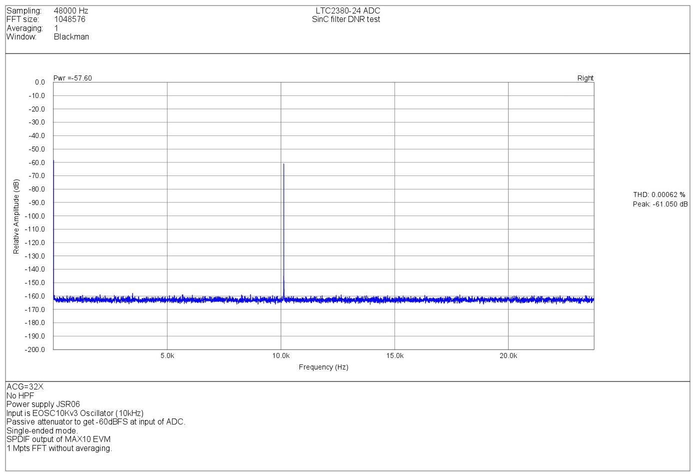
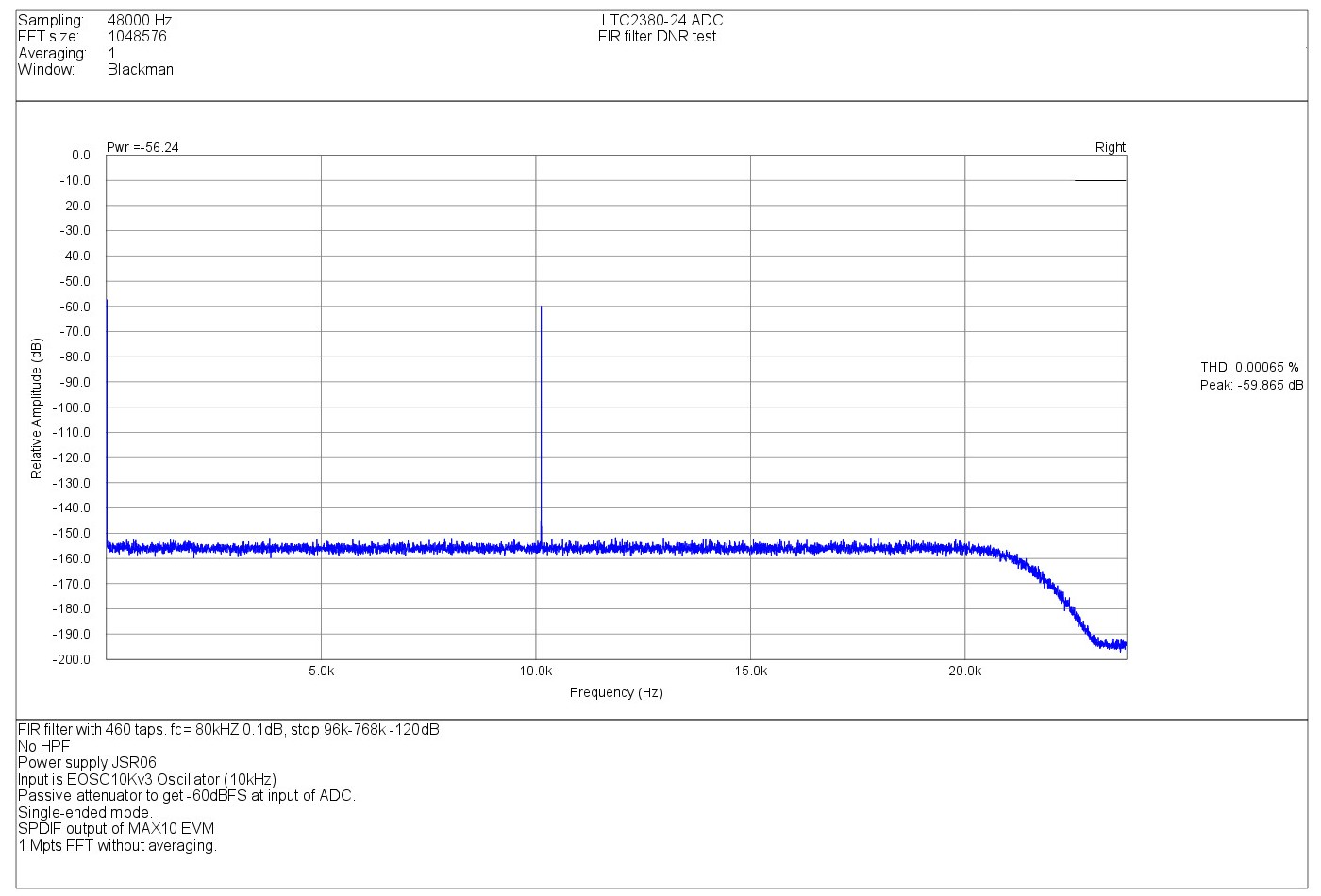
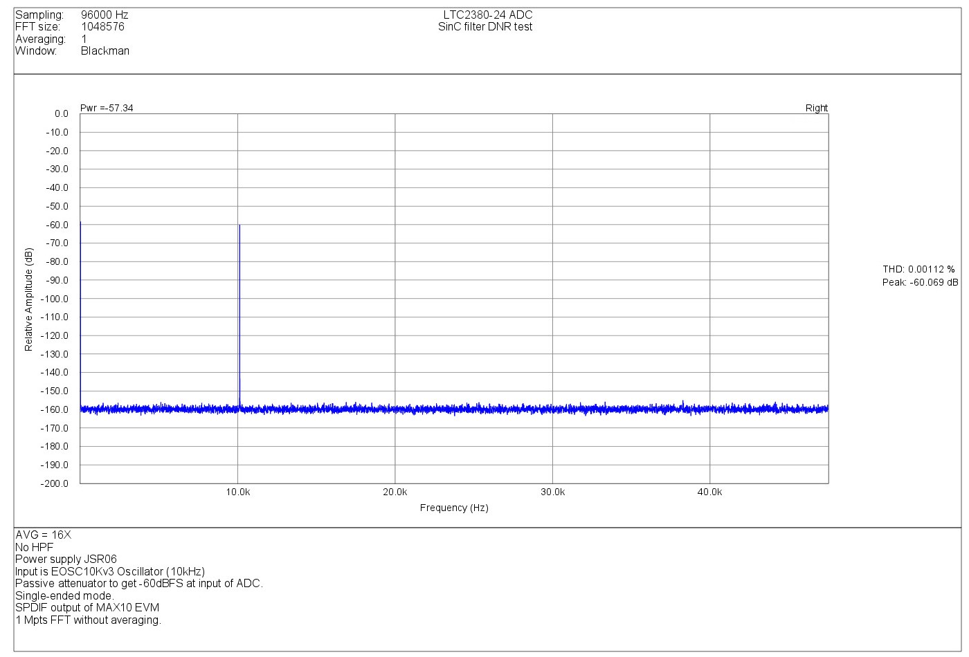
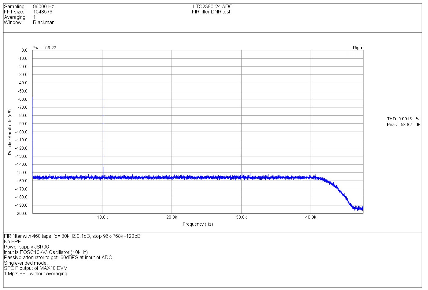
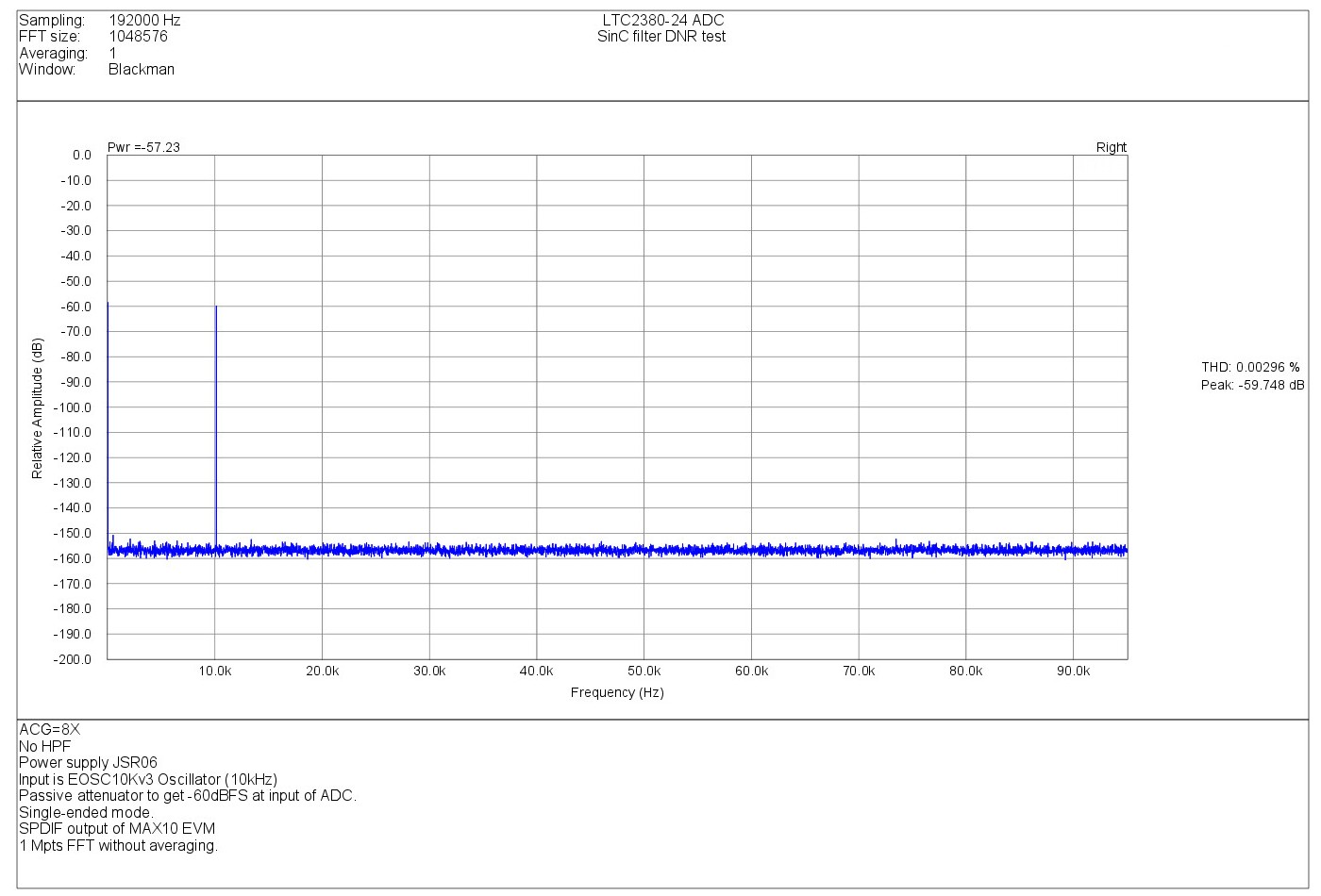
You can show below some measurements results of the ADC in different sampling rate
with the internal SinC averaging filter and with the FIR filter.
First, some DNR test at -10 kHz 60dB FS. (FS= 10Vpp).
The signal source is the EOSC10KV3 oscillator.+ Passive attenuator to set -60dBFS level.
All tests are made with 1Mpts FFT without averaging and Blackman weighting window.
SinC Filter 48kHz 32x mode.
FIR filter mode 48kHz (D=8 , Fs= 384 kHz)
SinC Filter 96kHz 16x mode.
FIR filter mode 96kHz (D=8 , Fs= 768 kHz)
SinC Filter 192kHz 8x mode.
FIR filter mode 192kHz (D=8 , Fs= 1536 kHz)
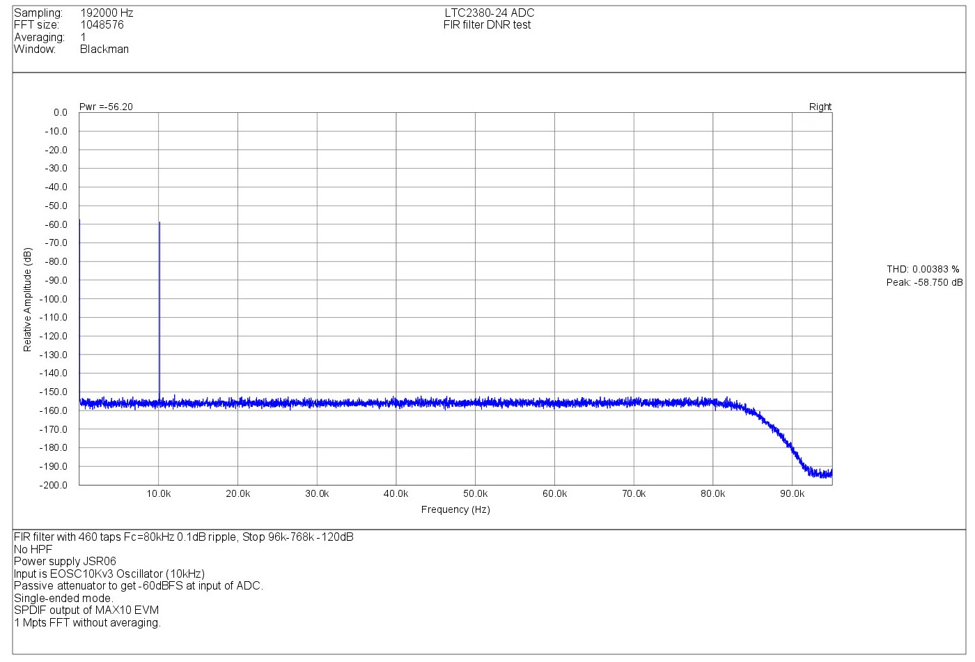
As you can show the spectrum is very flat and clean.
We show also the fast cutoff beyond 80kHz in FIR mode because
of it's very fast roll-of.
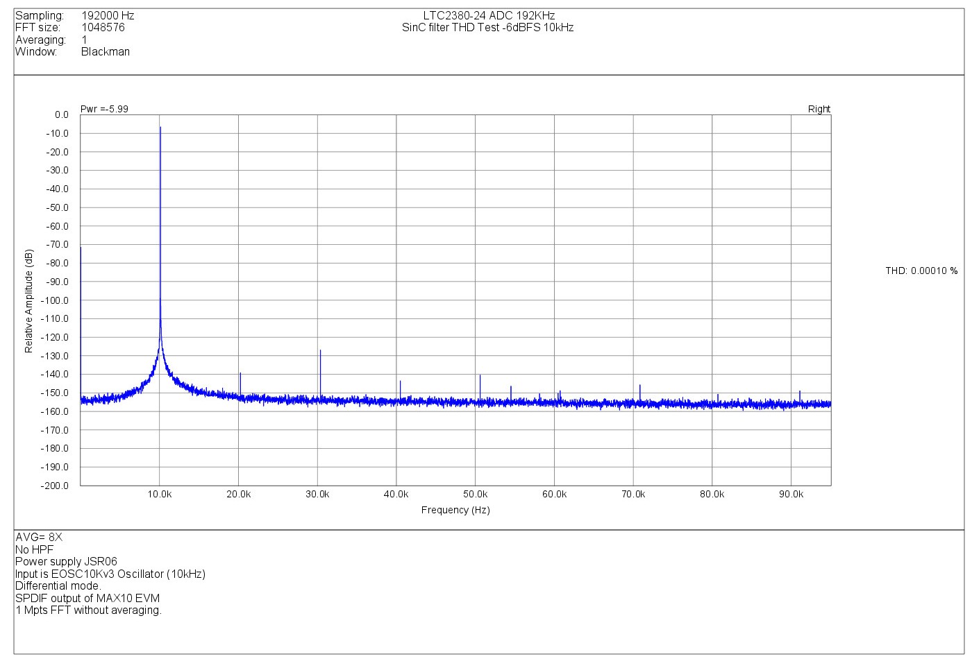
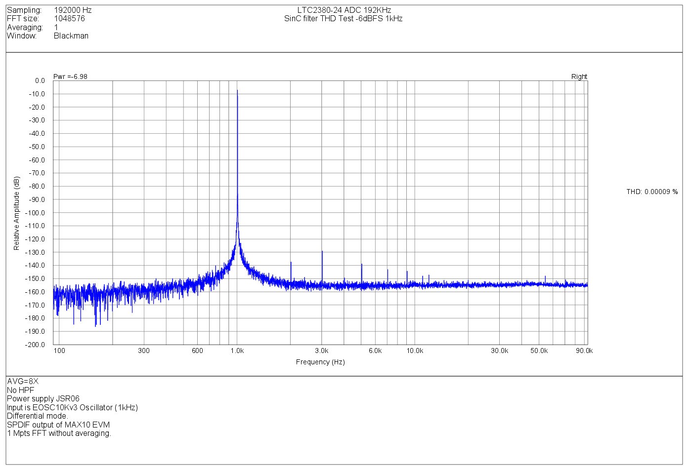
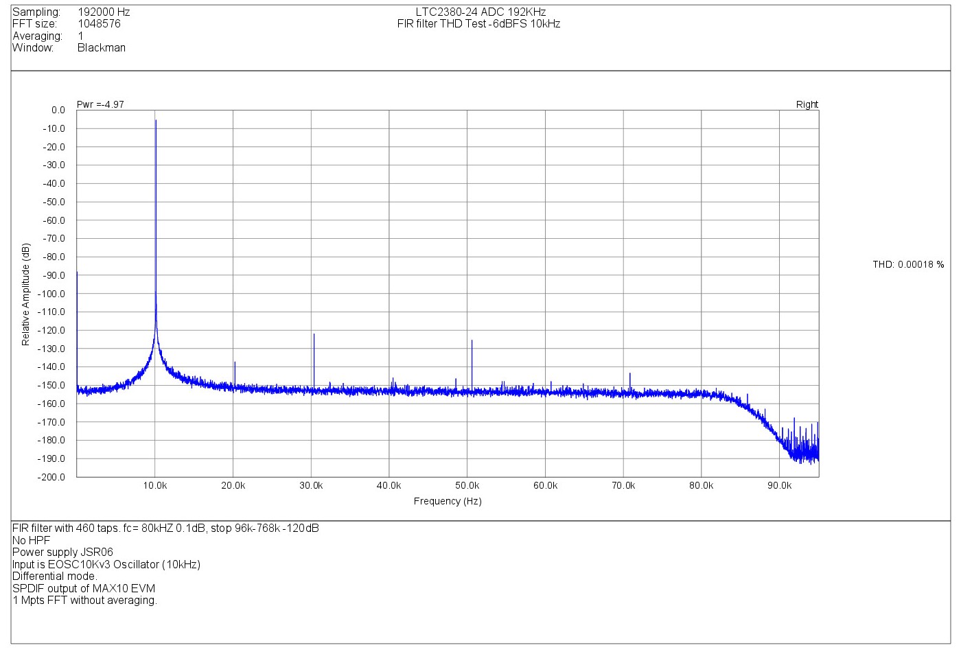
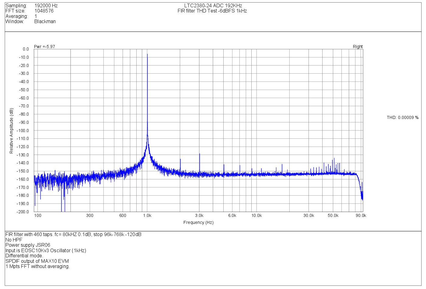
Now, some THD results at 1 kHz and 10 kHz and -6 dBFS level with
EOSC10KV3 1kHz and 10kHz versions.
These test are performed with SinC filter and FIR filter, 192kHz output sampling rate.
10 kHz -6 dBFS THD , SinC Filter 192kHz 8x mode.
1 kHz -6 dBFS THD , SinC Filter 192kHz 8x mode.
10 kHz -6 dBFS THD ,FIR filter mode 192kHz (D=8 , Fs= 1536 kHz)
1 kHz-6 dBFS THD ,FIR filter mode 192kHz (D=8 , Fs= 1536 kHz)
---
Now, the next graphs below allow to clearly show the practical result of decimating FIR filter used here.
We send a signal outside the Nyquist limit of the effective sampling rate (192kHz) :
a -20dBFS(1Vpp) level sine wave at 106 kHz.
The first graph show the results with the internal SinC filter only (8x mode), and the second with the external decimating FIR filter
implemented in the FPGA :
106 kHz-20 dBFS , SinC filter mode 192kHz 8x mode
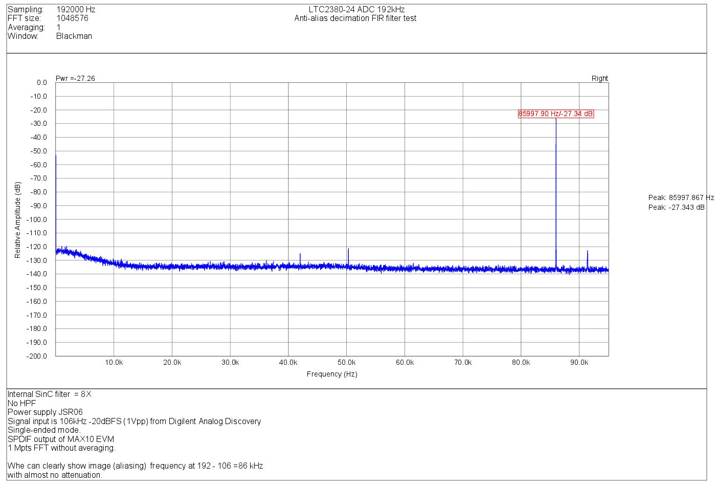
In SinC mode, the filter doesn't avoid aliasing and 106kHz signal is show as a 86kHz signal (192k-106k= 86k).
There is mainly no attenuation of the image (only a little from analog input filter and SinC).
106 kHz-20 dBFS ,FIR filter mode 192kHz (D=8 Fs=1536 kHz)
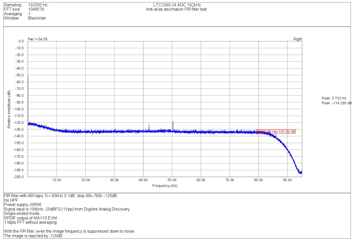
Now, when FIR mode is active, the alias image is buried in the noise floor.
So, FIR filtering avoid misleading measurements (under-sampling) and make the analog input filtering much easier.
Of course, any type of filter is possible in the design (FIR or RII) and think to try now to change between filters
banks on the fly.
I want also to create a little more friendly GUI and for this i purchased a neat LCD to display
some control informations and also if possible some measurements like :
And also (if i can) ;
Maybe others things if interesting ideas come (from you !)
The complete control of the display and all the measurements will be made by the CPLD.
So, again some job in the list....
Frex
Hello all,
Since my last post i work a lot on CPLD design and made many tests.
The design can now read the LT2380-24 ADC samples at it's full speed (even more..) of 1.536 MSPS
without internal averaging.
This require 100MHz SPI clock to get the 24 bits data between each sample.
This stream is sent in serial form to the MAX10 EVM for further digital processing.
For now, the CPLD include :
- A 500 taps x8 decimating FIR filter with 80kHz 0.1dB ripple pass-band and -120dB stop-band
from 96 to 768kHz (Fs/2). - 2x to 32x digital moving average filter
- A digital high pass-filter (subtracting-integrating) that allow complete DC calibration.
- LT2380-24 Internal Sinc filter selectable from 1x to 32x average.
The front/rear panel switches and leds (from left to right) functionality are :
- Power ON -- orange led indicated calibration in progress (blink) or offset reset (single short light)
- BNC1 and 2 -- Signal Inputs + and -
- 4 leds :
Orange = 192 kHz SPDIF output sampling rate
yellow= 96 kHz SPDIF output sampling rate
green= 48 kHz SPDIF output sampling rate
- Three positions toggle switch:
middle= SR 96 kHz
down = SR=48kHz
- 2 positions monostable toggle switch :
up for 1 s : reset DC calibration.
down : default position
- 2 positions toggle switch :
down = external moving average filter mode
- 2 positions toggle switch (the last at right):
down = Internal SinC filter mode
- 3 positions monostable toggle switch on rear (next to bananas) :
middle = default position
move down = no operation
All these operations mode allow user to choose between each of the better worlds.
You can show below some measurements results of the ADC in different sampling rate
with the internal SinC averaging filter and with the FIR filter.
First, some DNR test at -10 kHz 60dB FS. (FS= 10Vpp).
The signal source is the EOSC10KV3 oscillator.+ Passive attenuator to set -60dBFS level.
All tests are made with 1Mpts FFT without averaging and Blackman weighting window.
SinC Filter 48kHz 32x mode.
FIR filter mode 48kHz (D=8 , Fs= 384 kHz)
SinC Filter 96kHz 16x mode.
FIR filter mode 96kHz (D=8 , Fs= 768 kHz)
SinC Filter 192kHz 8x mode.
FIR filter mode 192kHz (D=8 , Fs= 1536 kHz)
As you can show the spectrum is very flat and clean.
We show also the fast cutoff beyond 80kHz in FIR mode because
of it's very fast roll-of.
Now, some THD results at 1 kHz and 10 kHz and -6 dBFS level with
EOSC10KV3 1kHz and 10kHz versions.
These test are performed with SinC filter and FIR filter, 192kHz output sampling rate.
10 kHz -6 dBFS THD , SinC Filter 192kHz 8x mode.
1 kHz -6 dBFS THD , SinC Filter 192kHz 8x mode.
10 kHz -6 dBFS THD ,FIR filter mode 192kHz (D=8 , Fs= 1536 kHz)
1 kHz-6 dBFS THD ,FIR filter mode 192kHz (D=8 , Fs= 1536 kHz)
---
Now, the next graphs below allow to clearly show the practical result of decimating FIR filter used here.
We send a signal outside the Nyquist limit of the effective sampling rate (192kHz) :
a -20dBFS(1Vpp) level sine wave at 106 kHz.
The first graph show the results with the internal SinC filter only (8x mode), and the second with the external decimating FIR filter
implemented in the FPGA :
106 kHz-20 dBFS , SinC filter mode 192kHz 8x mode
In SinC mode, the filter doesn't avoid aliasing and 106kHz signal is show as a 86kHz signal (192k-106k= 86k).
There is mainly no attenuation of the image (only a little from analog input filter and SinC).
106 kHz-20 dBFS ,FIR filter mode 192kHz (D=8 Fs=1536 kHz)
Now, when FIR mode is active, the alias image is buried in the noise floor.
So, FIR filtering avoid misleading measurements (under-sampling) and make the analog input filtering much easier.
Of course, any type of filter is possible in the design (FIR or RII) and think to try now to change between filters
banks on the fly.
I want also to create a little more friendly GUI and for this i purchased a neat LCD to display
some control informations and also if possible some measurements like :
- Actual sampling rate
- Type of filter
- DC/AC mode
- Averaging ratio in SInC mode
And also (if i can) ;
- Input Level in dB (0 to -120)
- Peak frequency
- Offset level in V
Maybe others things if interesting ideas come (from you !)
The complete control of the display and all the measurements will be made by the CPLD.
So, again some job in the list....
Frex
People say you can never judge how something will sound by graphs and measurement data alone but looking at the distortion patterns of this ADC I get the feeling it is going to sound very nice as well as being a very useful measurement tool.
Do you have any idea as to how long it may be before PCB/project will be available for purchase?
Do you have any idea as to how long it may be before PCB/project will be available for purchase?
Hello all,
I haven't post project news for some weeks now, but mainly because i am concentrated on advancement
of this and other project. So, it's time now to talk a little about it.
I worked a lot to connect an LCD display to the MAX10 FPGA board and to replace all the switches
by a single rotary encoder with integrated push button.
Now, all works fine.
By pressing the encoder for 1s, we enter in setting mode and the current parameters is blinking on display.
Then we can change it's value by rotating right(+) or left (-).
Another 1s press will exit from setting mode and settled value is frozen.
The parameters are :
All functions are easily set with the encoder as we see all directly on the display.
The LCD screen also display some interesting information on the incoming signal.
1 ) The main Input frequency of the incoming signal
From 000.1Hz to ~ 80.00kHz in a 4 digits auto-ranging counter,
with gate time from 10s to 10ms. The last "z" character indicator change in size to show the gate time
period of the counter (depending on frequency). Actually, the counter operate for input level from 0dB to about -80dBFS.
2 ) The incoming signal input level in dBFS[/U]
It is possible to show the peak input amplitude, or the power level of the signal, directly in dBFS.
The range of measurement is from 0 to -138.5dB with 0.25dB step.
I limited the output sampling rate to 192kHz for now, but only because i don't have any solution for now
that can receive higher bit-rate.
Another member help me from his side by developing a data bridge solution to allow sending audio data stream
up to 384kHz using USB link between my hardware and the computer instead of use of SPDIF now.
This bridge will allow to seen the system as en audio device and to used as one with any audio software.
I start also myself to work on another complementary solution that would enable to
send very high speed streamed data (1536kHz, 2 channels) by using FTDI USB3 bridge.
Anyway, even if that seem possible, in this mode the device will not be recognize as audio device.
So, it will require some post treatments to converts data from audio format (wav..) and then make post processing.
So, i really think that depending on the end application that both data bridges are very interesting,
i will do all my possible on the hardware to support both.
To answer on the previous charliecola question, i don't know when the project will be finalized.
Probably not before next year to be honest.
Even if much work has already be made, there is some job to be done before i designed a real prototype hardware.
Anyway, i'm on the way.
Note that i am currently open to suggestions on the design.
Regards.
Frex
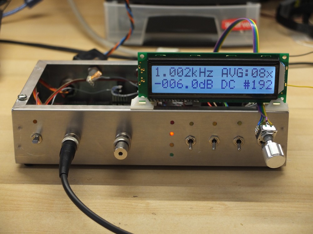
To finish, a picture of the system with the new display and menu :
The LCD view with it's menu and measurement .
I haven't post project news for some weeks now, but mainly because i am concentrated on advancement
of this and other project. So, it's time now to talk a little about it.
I worked a lot to connect an LCD display to the MAX10 FPGA board and to replace all the switches
by a single rotary encoder with integrated push button.
Now, all works fine.
By pressing the encoder for 1s, we enter in setting mode and the current parameters is blinking on display.
Then we can change it's value by rotating right(+) or left (-).
Another 1s press will exit from setting mode and settled value is frozen.
The parameters are :
- 1) Filter mode => SinC averaging filter or fast rollof FIR decimating filter
- 2) Averaging ratio in SinC mode => 1x to 32x (max value depend on sampling rate)
- 3) Input digital coupling => DC mode / AC mode / DC calibration mode.
- 4) Output sampling rate => 48kHz/ 96 kHz / 192KHz
All functions are easily set with the encoder as we see all directly on the display.
The LCD screen also display some interesting information on the incoming signal.
1 ) The main Input frequency of the incoming signal
From 000.1Hz to ~ 80.00kHz in a 4 digits auto-ranging counter,
with gate time from 10s to 10ms. The last "z" character indicator change in size to show the gate time
period of the counter (depending on frequency). Actually, the counter operate for input level from 0dB to about -80dBFS.
2 ) The incoming signal input level in dBFS[/U]
It is possible to show the peak input amplitude, or the power level of the signal, directly in dBFS.
The range of measurement is from 0 to -138.5dB with 0.25dB step.
I limited the output sampling rate to 192kHz for now, but only because i don't have any solution for now
that can receive higher bit-rate.
Another member help me from his side by developing a data bridge solution to allow sending audio data stream
up to 384kHz using USB link between my hardware and the computer instead of use of SPDIF now.
This bridge will allow to seen the system as en audio device and to used as one with any audio software.
I start also myself to work on another complementary solution that would enable to
send very high speed streamed data (1536kHz, 2 channels) by using FTDI USB3 bridge.
Anyway, even if that seem possible, in this mode the device will not be recognize as audio device.
So, it will require some post treatments to converts data from audio format (wav..) and then make post processing.
So, i really think that depending on the end application that both data bridges are very interesting,
i will do all my possible on the hardware to support both.
To answer on the previous charliecola question, i don't know when the project will be finalized.
Probably not before next year to be honest.
Even if much work has already be made, there is some job to be done before i designed a real prototype hardware.
Anyway, i'm on the way.
Note that i am currently open to suggestions on the design.
Regards.
Frex
To finish, a picture of the system with the new display and menu :
The LCD view with it's menu and measurement .
new SDR widget PCB group buy for 24/192kHz recording
hello
As to add others possibility to the ADC, i want to try using a SDRwidget USB interface board with my ADC.
So, because i don't have found one for sale i opened today a group-buy dedicated of the SDRwidget bare PCB.
This board allow 24bits / 192 kHz audio playback and record in any OS and is fully
open sourced. The group buy can be accessed HERE.
Regards.
Frex
Last edited:
This board contains an ADC. You are building an ADC.... what is the use for you?
Which interfaces will You use for the SAR ADC on this board and how will it be connected to the SAR?
//
Which interfaces will You use for the SAR ADC on this board and how will it be connected to the SAR?
//
hello
As to add others possibility to the ADC, i want to try using a SDRwidget USB interface board with my ADC.
So, because i don't have found one for sale i opened today a group-buy dedicated of the SDRwidget bare PCB.
This board allow 24bits / 192 kHz audio playback and record in any OS and is fully
open sourced. The group buy can be accessed HERE.
Regards.
Frex
The SDR widget has an AK5394 as I remember which is the best audio ADC I have tested. However its a well documented platform that should enable easy connection to the SAR ADC (after the FPGA). Most audio ADC's are pin programmed so you should not need new code to make it work. However you may be able to get Borge's USB board http://www.diyaudio.com/forums/digi...e-usb-interface-audio-widget.html#post2515807 and work from that. They share a lot. Borge should be able to help.
Another option that may be less work and overhead with more potential is to get one of the DIYINHK's XMOS boards Isolated XMOS 768kHz DXD DSD512(DSD1024) high-quality USB to I2S/DSD PCB - DIYINHK and redo the firmware. While the XMOS firmware is not "open source" the code is easily available from their web site with lots of useful pieces available.
Another option that may be less work and overhead with more potential is to get one of the DIYINHK's XMOS boards Isolated XMOS 768kHz DXD DSD512(DSD1024) high-quality USB to I2S/DSD PCB - DIYINHK and redo the firmware. While the XMOS firmware is not "open source" the code is easily available from their web site with lots of useful pieces available.
Hi Frex & all,
As Frex & probably also 1audio knows I'm interested in high sampling frequencies and - with some humbleness here because I'm not a programmer and I don't know how difficult this may be ;-) - would suggest that there's a focus beyond "presence", i.e. looking maybe a bit into the future. Thus, I would suggest a card that works up to 1.536 MHz (like the FTDI), yet with the option of up to 6 channels. I reckon that such a card may also be sellable to many more people (recording studios, recording system developers, other purposes, etc.) if it e.g. has the option of 384 kHz, 768 kHz & 1536 MHz data transfer rates. If it could include SPI, I2S and even parallel data transfer it may also accommodate high speed ADCs like e.g. the AD7760 ... but again, not being a programmer, I don't know how complex this is ...
Anyway, I'll be off on vacation in a couple of days so no further comments from me in some time.
Cheers,
Jesper
Hello,
TNT, the SDR widget use two boards, one MCU with USB and uC, and the analog board
with the AK5394A ADC. I only ordered the uC board because i want to try to use it as an USB bridge between my ADC and the computer and to see it as an audio device.
For now, my system convert the high speed SPI link of the LT23080-24 ADC in a SPDIF signal that is sended to my RME HDSP9632 SPDIF input.
With the SDR widget board i will no longer need to use the RME card because
i can easily replace the SPDIF signal from my CPLD by a I2S standard audio link sent
the the SDR uC board.
Is that more clear ? 🙂
Hello Demian,
As i remember from all my reading, the Borges design doesn't support input, it's only for audio out.
The original design from George Boudreau in the SDR widget support well the 192kHz I2S input
as this is the main function of the SDR receiver.
I think also that is very much DIY friendly solution than any other.
I have already own a DIYink board, and i had a bad experience with.
I'm also not much comfortable with firmware writing.
I found also that all XMOS board is really overpriced.
Regards
Frex
This board contains an ADC. You are building an ADC.... what is the use for you?
Which interfaces will You use for the SAR ADC on this board and how will it be connected to the SAR?
TNT, the SDR widget use two boards, one MCU with USB and uC, and the analog board
with the AK5394A ADC. I only ordered the uC board because i want to try to use it as an USB bridge between my ADC and the computer and to see it as an audio device.
For now, my system convert the high speed SPI link of the LT23080-24 ADC in a SPDIF signal that is sended to my RME HDSP9632 SPDIF input.
With the SDR widget board i will no longer need to use the RME card because
i can easily replace the SPDIF signal from my CPLD by a I2S standard audio link sent
the the SDR uC board.
Is that more clear ? 🙂
The SDR widget has an AK5394 as I remember which is the best audio ADC I have tested. However its a well documented platform that should enable easy connection to the SAR ADC (after the FPGA). Most audio ADC's are pin programmed so you should not need new code to make it work. However you may be able to get Borge's USB board http://www.diyaudio.com/forums/digit...ml#post2515807 and work from that. They share a lot. Borge should be able to help.
Another option that may be less work and overhead with more potential is to get one of the DIYINHK's XMOS boards Isolated XMOS 768kHz DXD DSD512(DSD1024) high-quality USB to I2S/DSD PCB - DIYINHK and redo the firmware. While the XMOS firmware is not "open source" the code is easily available from their web site with lots of useful pieces available.
Hello Demian,
As i remember from all my reading, the Borges design doesn't support input, it's only for audio out.
The original design from George Boudreau in the SDR widget support well the 192kHz I2S input
as this is the main function of the SDR receiver.
I think also that is very much DIY friendly solution than any other.
I have already own a DIYink board, and i had a bad experience with.
I'm also not much comfortable with firmware writing.
I found also that all XMOS board is really overpriced.
Regards
Frex
Thanks - so an I2S-to-USB board. Can the USB board work as I2S slave? I suppose we don't want any SRC on the ADC board but synchronous connection of the clock on the SAR board to the SAR ADC chip.
//
//
Frex- your skills with this stuff are really quite impressive. I have been told the XMOS firmware is not a quick think to get up to speed on. There are other much cheaper XMOS boards from China.
I thought Borge's USB board would support George's firmware. It would be worth checking. Also an ASIO driver would make a big difference getting Windows audio system out of the way.
I thought Borge's USB board would support George's firmware. It would be worth checking. Also an ASIO driver would make a big difference getting Windows audio system out of the way.
Frex,
Can the XMOS also be the clock master on the SCLK and LRCK, while receiving the MCLK from your ADC board?
If that is the case, I may have a solution for this.
Jens
Can the XMOS also be the clock master on the SCLK and LRCK, while receiving the MCLK from your ADC board?
If that is the case, I may have a solution for this.
Jens
USB board power solution - better not contaminate SAR board ground and others with foul DC/ground.
Isolators on I2S? Separate DC feed? If the ADC board is indeed the clock master, then nothing can really go bad downstream thinking about data integrity...
//
Isolators on I2S? Separate DC feed? If the ADC board is indeed the clock master, then nothing can really go bad downstream thinking about data integrity...
//
Hello,
Thank you Demian. About the USB interface board, i want to try to different system interface in order to choose the betters for each use. So, i want to test them.
JensH,
As probably in your design, the main ADC clock can be used as clock for the Xmos device and
so LRCK and SCK can be taken from the XMOS as all is synchronous from the XMOS/ADC clock.
Then what will be your suggestion ?
TNT,
Don't worry.I'm very concerned about signal integrity, as the high level of performance i want to reach will not support any design approximation.
So yes, there will be an isolation between the USB ground and the rest of the system.
Frex
Jens has excellent solutions for the isolation etc. with an XMOS interface. Some of this is a lot of work and its great when you can avoid reinventing the wheel.
You can also consider CM6631A, which is similar to the XMOS but the drivers are free. May require a Keil C51 (8051) license to compile the firmware framework. Not sure what XMOS requires or if it's free.
Hello all,
I received my SDRwidget PCB and will have parts very soon.
I continue to work on the design and i'm thinking about using
the ADC at it's full capability, viewing spectrum up to 768kHz (FS/2).
In fact, even if i design something that can output and send high sampling rate
to a computer (up to 768kHz), there is no analysis software able to work with,
so that would be useless (I know only that HpW can receive 384k).
After some reflexion, i think there is a smart solution, at least for analysis purpose.
With a "standard" 192k 24 bits USB link on the ADC, and any 192k compatible
software (almost all) it would be possible to perform "segment" analysis with 96kHz
bandwidth between 0 to 768kHz (8 segments of 96k).
That would be possible by using spectrum shifting by multiplying the digital data
by two quadrature reference carriers and then applying an Hilbert transform
to one and adding the I/Q outputs to remove image frequencies.
All of this can be done in digital domain and will not alter the signal.
By this way, with the 96k bandwidth of the software we can look a slice of the spectrum
in much wider range without need to transfer all data at full sampling rate to the computer.
A simple control on the ADC analyzer could be used to choose the slice of spectrum we want to analyze
(Carrier frequency selection). I think that all these stuff can be implemented in the FPGA.
....
Frex
as long as you can save the data, .wav has GHz sample rate limit sample rate limit
plenty of free SW handles .wav, other formats, have fft, spectrograph, no sample rate limits
Python and SciPy libs have most anything you need
Matlab has a free, open source work-alike: Octave
SciLab is well supported too, also similar to Matlab
plenty of free SW handles .wav, other formats, have fft, spectrograph, no sample rate limits
Python and SciPy libs have most anything you need
Matlab has a free, open source work-alike: Octave
SciLab is well supported too, also similar to Matlab
- Home
- Design & Build
- Equipment & Tools
- SAR ADC for high performance audio ADC project [LTC2380-24]