No.... of course you don´t. The relay is "on", but bad contacts result in no sound.But I don't hear any clicks from the relay between on and off
When turning up volume, the current "breaks through" the corrosion, thus making contact.
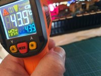
Now the bias is 26mV on both channels. I don't know why I thought that when it's hot the problem gone but it's not. Sorry for the confusion.
Let say that it's better when it's hot than when it's cold but it's not stable when it's hot. BTW the difference in °C between right and left is 10°C when the right side is hotter. Left 40°C right 50°C
About checking the voltage across the white resistors it's a bit difficult there are total of 16 resistors and 2 meters. I'm afraid put the mini hooks across the resistors in live. So I will need to shut down the amp 8 times for cold condition and 8 time for hot condition.
4 times 26mV, right ? left hot, left cold, right hot, right cold.Now the bias is 26mV on both channels.
Yeah...... Life really sucks 🤣 🤣About checking the voltage across the white resistors it's a bit difficult there are total of 16 resistors and 2 meters. I'm afraid put the mini hooks across the resistors in live. So I will need to shut down the amp 8 times for cold condition and 8 time for hot condition.
In analogus situations (eg. temperature testing a circuit in an environmental chamber), I tack-solder lengths of hookup wire to each test point of interest and bring the wires to "the outside world." Typically, I strip about 1/2 inch of insulation from each end and push the ends of each wire through small holes in a piece of corrugated cardboard. This keeps the all test points safely separated and easily selected for measurement. I pencil labels on the cardboard at each hole to ID each test point.
If the test wire presents problematic coupling to the circuit under test, I often tack a series resistor between TP and the connecting wire to help tame susceptibility. Heat shrink insulates the resistor-wire connection.
All this preparation is tedious, but guards against mishaps and is time saving in the long run.
Good luck.

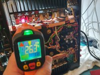
I turn on the amp now and this amp drives me crazy. The amp cold and for at least 5 minutes the sound appears on the both channels and after a time it start to make the problem with right side and again after it becomes worm it's again OK. The resistors on problem side (the right side) are much cold then left side but the temp on the transistors are opposite right side hot left side 10°C less. Green right red left (for the resistors).
Attachments
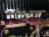
On right channel the temp of the 2 last resistors are higher than the rest. On the left side the temp is +/- the same on all of them. OK I will try tomorrow to check the voltages across the resistors. Maybe bad 2 power transistors on the right side that are not in the spec.
Attachments
When the problem appears and I rise the volume the right channel becomes alive and when turn lower the volume right channel still there for a while.
I love this amp. This amp is really a very good amp. Incredible sound. Very natural. Channel separation and good sound without any tone control. I enjoyed the music directly without the preamp.
That's why I asked you to measure every resistor voltage 😉Maybe bad 2 power transistors on the right side that are not in the spec.
And the two neighbouring resistors ?On right channel the temp of the 2 last resistors are higher than the rest.
2 corresponding transistors temperature ?
If those 2 resistors are hotter, it means more current, so you will measure higher voltage.
Something shorted / partly shorted / open.
Last edited:
Do you have a scope? When the amp acts up, check top of pot element and wiper to determine if pot is culprit. If necessary, bring out test wires from various points in signal path so that you can probe when misbehavior occurs. Use divide and conquer search to localize the intermittent.When the problem appears and I rise the volume the right channel becomes alive and when turn lower the volume right channel still there for a while.
Good luck!
1:30am quick guess:
The 2 Mosfets or 2 resistors which are direct neighbours of the hot resistors are open = bad. So no current flowing, Mosfet and resistor are cold.
Because, seen from board edges, 1 pair of parallel Mosfets on both sides of the pcb. If one Mosfet / resistor fails and is open, the parallel part must take double current to establish the idle bias and get hot.
Mosfet open or resistor open.
Or bad solder connection on resistors, unlikely...
Best check the 8 0.22ohm resistors of bad channel as next step.
Last edited:
Thanks for all the comments. Yes I have a scop. I will check today voltage across the the resistors. When I turn on the amp, when the amp is cold, at the beginning the right channel act like it should for the next 5 minutes. The behavior is like parabola.
The pcb has those forklike contacts on the output FETs. You could measure there, the 3 points give you: bias voltage, gate voltage, rail voltage.I will check today voltage across the the resistors.
- Home
- Amplifiers
- Solid State
- Sansui Alpha AU-907i MOS Limited