There's no voltage drop between the input and output section. Thus no current across R1 either.
First wind the output voltage adjust trimmer all the way down.
Then measure if Q2 shows about 0.6V Vbe (DC between base & emitter).
First wind the output voltage adjust trimmer all the way down.
Then measure if Q2 shows about 0.6V Vbe (DC between base & emitter).
Not use it, follow Salas advice.I can try this
I want to wait till Salas responds though
I hope it works!
Mark
Remind me what was the situation?It’s a mod suggested by Salas.

Not enough mA of Idss at J1 and used other component with other pinoutRemind me what was the situation?
So we made some some special direct connection skipping its source resistor?Not enough mA of Idss at J1
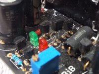
I have some improvements even with the pot turned all the way down V is 5.2V
Rf is cooking and smelling
D1-4 are hot
Is this a stable situation?
I can heatsink the diodes
Up the wattage for Rf
But V needs to be 5V
Rf is cooking and smelling
D1-4 are hot
Is this a stable situation?
I can heatsink the diodes
Up the wattage for Rf
But V needs to be 5V
SurelySo we made some some special direct connection skipping its source resistor?
From voltage drop across Rf divided by its value we will derive current. How much is indicated?
At least your target vout has now been nearly achieved.I have some improvements even with the pot turned all the way down V is 5.2V
What is Rf's Ohmic value and Wattage? Did you use more than 0.33Ω?Rf is cooking and smelling
- Home
- Amplifiers
- Power Supplies
- Salas SSLV1.3 UltraBiB shunt regulator