I'm getting ready to install my newly assembled Ultra Bib units into a DCG3 preamp. For this use, how much heatsinking is required, prefer conservative long life sinking. I am assuming the attachable stamped heatsinks are not sufficient, I havent seen anyone use those.
Are something Like these possible? Not necessarily THIS one, but this style. I've used something similar in the Pearl 2's regulator section, but taller than this one.
https://www.mouser.com/ProductDetail/CUI-Devices/HSE-B20254-035H-01?qs=5aG0NVq1C4yjFNoXzobJsA==
If this style isnt sufficient, I have also considered as many here have done, clamping to the floor of the chassis. The chassis is from the Diyaudiostore. 17 x 15 4 inches tall so lots of room. The covers are fully perforated both top and bottom. It has one of those perforated inner base plates. It is heavier steel, but has the perforations....careful "positioning" can get the mosfet parts mostly over the solid parts of the base plate....will this be sufficient? I have seen people here do this to the floor of the standard pan without the base plate in DCG3 applications, seems like this base plate might be better.
If those arent good, then I guess its separate aluminum heatsink sort of like I used for the mosfets in the DCG3, except smaller, My DCG3 heatsink is a bit over sized. I wanted this pre to be in a larger chassis, I knew the DCG3 generated heat, these regulators do as well. I am also adding the MUSE volume control and its associated power supply. It is plenty large and well ventilated. Not exactly a compact build! The standard power supply will be going into a much more compact ( Diyaudiostore Galaxy chassis ) version of DCG3.
Russellc
C2 is recommended to be "audio grade", but not C1? in the stage after rectifier this type of capacitor is not recommended or is it irrelevant?
(nichicon FW a bad choice for C1?)
can someone explain?
(nichicon FW a bad choice for C1?)
can someone explain?
Technically you may use any type you prefer for C1 & C2. For C3 you just have to check its 100kHz ESR spec must be within the recommended range noted on the schematic for stability reasons. Nichicon KG, FG, and KZ as well as UES have been very popular in the builds shown here. FW is not so much seen for C1 although its analogous. Maybe because not snap in that fits the board steadier.

Hi, Salas.
I would need shunt psu for preamp and need advice about CCS settings and choose heatsink for output mosfet to stay cool.
My preamp needs +/-24VDC and 50mADC.
I have two toroids with double secondaries that gives me 2x24VAC, each toroid is 30VA.
So with your calculation from post #1 i got CCS set to R1 = 600/ (100mA spare + 50mA needed for preamp) = 4R and i will use 3R9 CPF2, this is 2W vishay dale metal film resistor.
Dissipation of M1 is: (32VDC-24VDC) x 150mA = 1,2W.
Dissipation of M2 is: 24VDC x 150mA = 3,6W.
So total dissipation is: 1,2W + 3,6W = 4,8W for positive regulator and 4,8W for negative regulator...total for both regulators is: 9,6W that needs to be passive cooled with heatsink.
So i want put all 4 TO-220 mosfet on one heatsink and i found this with 3.3K/W:
https://www.fischerelektronik.de/we...s/$catalogue/fischerData/PG/SK18/search.xhtml
Is is 50mm in height so from diagram i see it have temperature resistance of 3.3K/W....
Now lets calculate temperature of heatsink when we have 9,6W on it to cool it:
9,6W x 3.3K/W + 25C (ambient temperature) = 57C will be heatsink temperature.
My question is is this OK for long term working for preamp psu or not?
I mean 57C for M1 and M2 mosfets is this very high temperature for them or i should find another heatsink for example eith 2K/W?
What is recommended temperature for M1 and M2?
I went to the "drop" site but clicking on add to cart does not work, just Keeps spinning. Am I at the correct site?The Massdrop 6XX is by far the better value proposition. Analogous to the 650 but at $240.
Russellc
Got 4 sinks for the regulators, and a larger one for the DCG3's MOSFETs on new build. Should be here a a couple of days.Decided to use separate heat sinks, like used for DCG3, but smaller. HeatsinkUSA to the rescue.
Russellc
Russellc
@ronovar
3.9R R1 even 1W will plenty suffice (0.6V*0.15A=0.09W dissipation). 3.9R is a typical part value to find
M2 dissipation is 24V*0.1A=2.4W because IbM2=150mACCS-50mA IbPreamp i.e. 100mA burned on M2
In reality expect around 30V rectified after losses with 24V Tx in a CCSed reg so 30Vin-24Vout is 6V*0.15A=0.9W for M1
Thus 0.9+2.4W=3.3W x2=6.6W or 47C on your 3.3C/W sink when using your 25C room ambient temperature condition
There? https://drop.com/buy/massdrop-sennheiser-hd6xxI went to the "drop" site but clicking on add to cart does not work, just Keeps spinning. Am I at the correct site?
Russellc
Drop them an email if there's a site bug? (pun intended) 🙂
These Mosfets are tough. They could go -55C to +150C internally and still work. The universal problem is that materials deteriorate faster in time the hotter they get. Quickly shortening lifespan. Practical sink temperature should arguably be up to 50C when installed inside a box and up to 65C if outside a box. But those assumptions vary on what you consider acceptable to handle.What is recommended temperature for M1 and M2?
Hi Salas,
i'm struggling with space constraints to fit the UltraBib with a substantial heatsink in a previous project already boxed, so i ask if it's safe to mount the mosfets on the sink and then go from their pins to the PCB with no more than 2 inches of wire without any problem. Maybe is it advisable to use ferrites on the gate?
Thank You.
I don't know if it will stay stable, possibly, but never seen report on one installed like that yet in the thread. I would move the gate resistors R2 R9 directly on the pins at least.
Many thanks for your faster than light reply. While i was preparing the move of the mosfets with their gate stopper, i received a message from Mouser. FQP3P20 and FQP3N30 are in end of life mode. So i'll find another arrangement to prevent frying them.
Which other mosfets can you recommend in this position?
Again many, many thanks.
Which other mosfets can you recommend in this position?
Again many, many thanks.
IRF610/9610 alt M1s for lower than 1A CCS setting. IRF620/9620 for heavy CCS settings up to 3.5A.
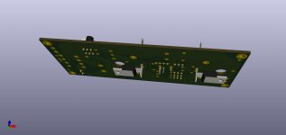
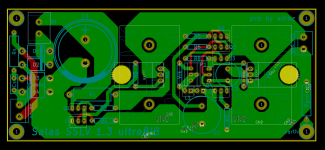
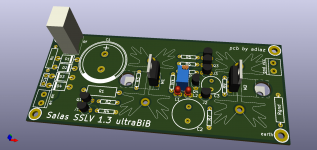
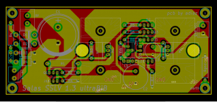
My pcb design is finished. I did it to be able to mount the mosfets on SK129-STS heatsinks or also mount them on the bottom of the box if it is aluminum. Both options available.
Rectifier diodes can be mounted from MUR220 to MUR460. Capacitors C2 and C3 are Nichicon muse BP ES, for 220uF/50v and 47uF/50v.
Next I will send to manufacture JLCPCB...
Rectifier diodes can be mounted from MUR220 to MUR460. Capacitors C2 and C3 are Nichicon muse BP ES, for 220uF/50v and 47uF/50v.
Next I will send to manufacture JLCPCB...
Attachments

- Home
- Amplifiers
- Power Supplies
- Salas SSLV1.3 UltraBiB shunt regulator