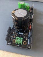
Do you find any problem?
Or shouldn't I have posted any pics of the pcb?
I can delete if you see fit
Or shouldn't I have posted any pics of the pcb?
I can delete if you see fit
I can't see of problems in a board without practical experiment. I just know its not inherently a very tame circuit because of large OL bandwidth etc. and there are ways to oscillate due to layout. I have been through failed prototypes until official board. That is why I genuinely wished good luck on first try with your personal use prototype. By the way, with this Mosfets mounting strategy only bottom sinking is able for some useful dissipation. The alternative board level sinks are just useful for rather moderate dissipation application with shunt regs. Maybe you could avoid them altogether to make it smaller if their absence helps for that in a way.
You are right. In principle, my consumption requirements at 5v are only 70mA per device, with a small heatsink it is enough and the assembly is easier. But in other future projects, maybe I need more power.
However, as a precaution, I will make a first attempt by manufacturing the pcb at home to test if there is oscillation and if it works correctly, if everything goes well, I will order it to be manufactured.
Thanks for your comments...
However, as a precaution, I will make a first attempt by manufacturing the pcb at home to test if there is oscillation and if it works correctly, if everything goes well, I will order it to be manufactured.
Thanks for your comments...
Hello. I'm having some problems with making these boards working. My knowledge is very limited, but I'm really trying my best.Did you turn the trimmers in both directions? Clockwise & anticlockwise?
Are they official boards so we can exclude routing mistakes? One thing to keep, its a systematic error. Can't be performing same way wrong in four sections just because of bad luck. So lets look for that mistake or failure.
Maybe its about M1 or Q2. More probable. First a thorough visual inspection. Make sure they are the proper types. Then make sure no other component is populated systematically wrong either for type or orientation. A photo would also help.
Correct Vgs for the IRF Mosfets is 3-4V (voltage between legs 1 & 3). For FQP type 4-5V. Correct Vbe for BC transistors is 0.55-0.65V (legs 2,3). Good voltage over 270 Ohm resistors is 270mV-540mV leg to leg. If you see no voltage drop on such a resistor, means the associated JFET does not conduct. Do check all those voltages.
I've build two sets of boards, but I lay two of them work as intended, thanks to this message I've narrowed the problem a bit. My IRF MOSFET only measures 0.58 between legs, the MOSFET itself was provided by the group buy, so I assume is legit. Where should I look to find the origin of the problem?
One thing I did wrong when buying the resistors is that I bought dale rn60d but they are physically bigger than the room for them on the board. Is that important?
The boards not working output 1.4x volts both positive and negative. (One of them outputs nothing, but I will leave that one for later) and also leds do not work
Also is there a book/webpage I can read in order to understand power supplies better? I don't intend to be and expert by any means but at least to know what I'm doing because I have no clue as to where to look when there is a problem.
I have already built a whammy, a dam 1121 and another couple of headphone amps, but this is proving to be a challenge.
Thanks in advance for any help.

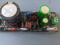
Of course! This is the one I've been tinkering with. I've already changed the trimmer because it didn't changed the resistance when turning it, but it made little difference.
Attachments
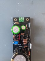
Hi, because the brown resistors are big* for this board, curving thick legs creating tensions, the soldering has blobs and I am suspicious of sneaky cold or buried no continuity spots. Especially between layers via eyelets. Two other sections assembly had worked for you while using the same kind of active and passive parts? Have you verified circuit continuity vs the schematic with the DMM's continuity mode buzzer?
*RN60 values selection set from Israel?
*RN60 values selection set from Israel?
0.58V is legit only as Q1 Vbe between its pins 2 & 3 or across R1. Those are same points electrically because R2 does not drop practical voltage. M1 FQP between its outer pins reaches over 4V when properly conducting in this circuit and IRF M2 3V or more.My IRF MOSFET only measures 0.58 between legs, the MOSFET itself was provided by the group buy, so I assume is legit.
Hi, because the brown resistors are big* for this board, curving thick legs creating tensions, the soldering has blobs and I am suspicious of sneaky cold or buried no continuity spots. Especially between layers via eyelets. Two other sections assembly had worked for you while using the same kind of active and passive parts? Have you verified circuit continuity vs the schematic with the DMM's continuity mode buzzer?
*RN60 values selection set from Israel?
Yes, two other sections where built and they work fine. All active and passive components are the same across al boards (I´ve spent quite some time reviewing every part is correct and it´s where it should be)0.58V is legit only as Q1 Vbe between its pins 2 & 3 or across R1. Those are same points electrically because R2 does not drop practical voltage. M1 FQP between its outer pins reaches over 4V when properly conducting in this circuit and IRF M2 3V or more.
I haven´t verified continuity, but sounds like something I can do this evening.
I dont´understand the (*) I ordered RN60 from Spain but I´m not sure where Mouser shipped them from.
""I am suspicious of sneaky cold or buried no continuity spots"" this you say makes sense to me. Another thing that happend is that I marked a third section (a negative one) as "working" but the following day it wasn´t working anymore. Could this be cause by that? Also while I was soldering, the tin was not flowing properly to the front side of the board properly. While doing it I wasn´t sure wether this was normal or not, but I feel it isn´t normal as I read more about how to solder.
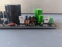
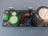
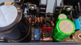
The board on the pictures from yesterday was resoldered from above trying to "fill the gaps" I will attach a pic of one of the boards that hasn´t been touched since I soldered it the first time so you can see better hoy I soldered it the first time. In the pic I see that the "holes" on the transistors are more or less filled, but on the resistors the seem to be empty, am I correct in that observation? is that because of the resistor being too big (and me not having very good skills) isn´t it?
Oh and 0.58v was measured on the outer legs of the IRF mosfet, which shouldn´t be the case. I didn´t explan myself properly on the first message.
It´s looking more and more like I will have to replace the resistors? That is going to take some time, but it´s the cost to learn 🙂 so It´s ok.
Thanks a lot
Attachments
(*) There was a popular ebay seller of legit RN60s that you could pick values for a nice price. I wondered why not the easier to fit 1/4W type that is why I asked if you got them from there.
If for cold solder joints, sneaky problems may occur. Since two other sections had worked with the same parts it could be an assembly issue or static discharge could have compromised some Mosfets during handling and soldering. Turn up the temperature of your soldering iron for this board if it has such a facility. Or use a fatter chisel type tip.
Some half filled pads can look suspicious but not the culprit and another good looking joint maybe has the bug in the end. Best to test electrically.
Try to see if continuity testing will verify all connections vs the schematics. Because it will be frustrating to remove components from a dual layer thick copper board just on suspicion if without a vacuum desoldering station. If continuity shows nothing wrong, try to remove M1 & M2 and see if they are good. M1 first. Do you have a component tester? Else there are guides on how to test Mosfets with just a DMM if you Google it up. You don't need to remove the resistors if they are doing the job and have verified circuit connections. But do check if there's a wrong resistor value systematically misplaced somewhere in the non working assemblies. The RN60s have large value code print but also use Ohmeter when in doubt.
...Also go to the small transistors and fets, try test basic diode behavior. Can find broken ones without strict need to remove from board first.
One question that I have doubts, I am going to use three low noise 5v power supplies in a Dac.
What is better, to use a single output of the 9vac transformer for the three power supplies or to use three independent secondary of 9vac transformer for each source?
What is better, to use a single output of the 9vac transformer for the three power supplies or to use three independent secondary of 9vac transformer for each source?
Another question...
BC560 is obsolete and I can't find it in reliable stores.
BC556 or BC327-40 can be possible substitutes?
BC327-40 I think it has less noise than BC556, right?
BC560 is obsolete and I can't find it in reliable stores.
BC556 or BC327-40 can be possible substitutes?
BC327-40 I think it has less noise than BC556, right?
Last edited:
-You MUST use three independent secondaries
-Don't substitute BC5xx for Q2 Q3 with BC3xx
BC327 is slow for those positions, the reg will oscillate. I tested that during development.
BC556 should work but prefer BC559 because better in noise. 30V spec but in 5V regs no worries.
-Don't substitute BC5xx for Q2 Q3 with BC3xx
BC327 is slow for those positions, the reg will oscillate. I tested that during development.
BC556 should work but prefer BC559 because better in noise. 30V spec but in 5V regs no worries.
Last edited:
Thanks!!!
Ok, BC559C if it is available in trusted stores. And I will use it for 5V output.
If in the future I want to use this source in 35v output, BC556C, will it work well?
Other alternative?
Ok, BC559C if it is available in trusted stores. And I will use it for 5V output.
If in the future I want to use this source in 35v output, BC556C, will it work well?
Other alternative?
From post#1 footnotes "BC559 can be used up to 30V output. BC556 for 31V-45V output" Mouser has BC559CTA.
Alternatives could be types with comparable Vceo, Cob, Ft, specs. Possibly with different pins order though.
Alternatives could be types with comparable Vceo, Cob, Ft, specs. Possibly with different pins order though.
Hi,
1) More than 100uF is no problem, maybe bit of a benefit actually, use what you got
2) 3V in-out will work up to a big current but 5V is recommended for a "stiffer" CCS
From the pdf build guide's last paragraph:
The reg works even with less than 5V difference because
CCmA weakening starts only at Vin-Vout <1.7V for ~200 CCmA settings. At 600mA CC it starts
weakening at Vin-Vout <2.5V. But more voltage space allows for mains play and for better M1's
parasitic capacitance.
Thanks Salas - appreciate your work.
I'm aiming for ~ 300mA CC so I'm reading from the above that 3V Vin-Vout won't experience any weakening.
Just an update on the above, the regs work fine with 3V Vin - Vout, however since it's DIY I got a new set of pre-regs for 5V Vin - Vout and the analog board attached to the SSLV sounds subjectively better. (A reminder that I've built a 2 chassis solution, with rectification and pre-regulation in the PSU chassis, and the SSLV regs with the audio boards in the other chassis.) Moral of the story for me is that even if you're using a pre regulator aim for the 5V difference.
Thanks again.
They dropped them to 219.00 and I couldn't resist.There? https://drop.com/buy/massdrop-sennheiser-hd6xx
Drop them an email if there's a site bug? (pun intended) 🙂
Russellc
Dear Salas I am planing R1 and need your help to clarify a few things.
UltraBiB will be powering Wayne BA2018 linestage with a few changes.
According to simulation one channel will consume 44mA, 88mA total.
It is said in the guide that after R1 formula I should add 50-150mA extra.
I am a bit lost how much extra should I add in cases:
1. One UBiB powers one channel (dual mono)
2. One UBiB powers both channels
Should I add 2x of extra to power both channels with one UBiB?
Or should I think of consumption as a whole?
Either 44mA or 88mA and add extra to that value.
My estimate calculation for now is:
1. range from 6.4R (50mA extra) to 4.1R (100mA extra) - For dual mono
2. range from 4.3R (50mA extra) to 3.2R (100mA extra)
- Home
- Amplifiers
- Power Supplies
- Salas SSLV1.3 UltraBiB shunt regulator