I have to admit that I have not read all 162 pages, but I have a question.
Is there a link to a page that itemizes appropriate applications for this LV regulator?
Is this reg good to provide a voltage reference for an op amp comparator for a shunt regulator?
Best,
Robert
Is there a link to a page that itemizes appropriate applications for this LV regulator?
Is this reg good to provide a voltage reference for an op amp comparator for a shunt regulator?
Best,
Robert
The extra current is specified per PSU unit. For internal use on top of peak load per unit.Dear Salas I am planing R1 and need your help to clarify a few things.
UltraBiB will be powering Wayne BA2018 linestage with a few changes.
According to simulation one channel will consume 44mA, 88mA total.
It is said in the guide that after R1 formula I should add 50-150mA extra.
I am a bit lost how much extra should I add in cases:
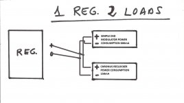
1. One UBiB powers one channel (dual mono)
2. One UBiB powers both channels
Should I add 2x of extra to power both channels with one UBiB?
Or should I think of consumption as a whole?
Either 44mA or 88mA and add extra to that value.
My estimate calculation for now is:
1. range from 6.4R (50mA extra) to 4.1R (100mA extra) - For dual mono
2. range from 4.3R (50mA extra) to 3.2R (100mA extra)
In your application:
For dual mono I suggest ~150mA CCS setting in each
For a single shared reg I suggest ~200mA CCS setting
-No such a page that I am aware of. All information critical for this design is either texted, uploaded, or linked in post#1I have to admit that I have not read all 162 pages, but I have a question.
Is there a link to a page that itemizes appropriate applications for this LV regulator?
Is this reg good to provide a voltage reference for an op amp comparator for a shunt regulator?
Best,
Robert
-Yes if used with a Zener reference instead of its variable resistor reference (trimmer). There are details about that in the pdf build guide
Understood.The extra current is specified per PSU unit. For internal use on top of peak load per unit.
In your application:
For dual mono I suggest ~150mA CCS setting in each
For a single shared reg I suggest ~200mA CCS setting
Thank you!
One more words about heat dissipation.
I planed output 16.5V, 200mA. On input had 22V transformer. It was extreamly hot. But then read carefully manual:
I planed output 16.5V, 200mA. On input had 22V transformer. It was extreamly hot. But then read carefully manual:
Set transformer voltage to ~18V. And luckily => power dissipation significantly decreased.Dissipation: M1W=(Vin-Vout)CCmA. M2W=Vout(CCmA-load_mA).
More than 150mA spare gradually adds current noise and much more spare mA drastically increases
M2's temperature and slides its characteristics. This regulator has low output impedance even with
100mA spare. So its good practice not to run it with too much spare current on purpose or in neglect.
Last edited:
Dear Salas,
I want to use your regulator to bring a 12 volts battery down to 6 volts for a MUTEC MC3+usb.
Will the output voltage of the ULTRABIB follow the battery proportionately as it declines from 13.5 to 12 volts?
I searched to see if this had been asked before and could not see such a question so I hope I am not repeating.
THANKS and take care,
Another question - actually I need confirmation.
The device I want to power uses a MEAN WELL 6 volts smps - it draws 10 watts maximum (per the spec sheet) from the mains.
Would this go over the ULTRA BIB's limit? I think it does - not substantially but enough to make it not the best choice for this?
If my assumptions are correct this would require a 0.3 ohms resistor in R1. Is that allowable?
Please let me know if this is correct. Though I would be glad to hear it is not!
Thanks,
That's 2A CCS setting and its heavy enough. M1 should be a stronger type in this case. Say IRF9630PBF. Still a shunt reg wastes energy in heat when the load cruises much lower than its max demand occasion. You could try monitor the device for consumption pattern before you decide. The popular Kill A Watt wall meter or alike could help.
*Given the Mean Well can't be 100% efficient, deduct 5-10% of what Wattage it draws from the mains for what the circuits it feeds really draw.
And being supplied by a battery there will not be any ripple to deal with. I just need it to reduce the voltage more than anything else.
I read an earlier post from a fellow who wanted to use it with Rothacher's amplifier and you did not faint so I think I will give it a try!
First to check which mosfet I have in place ... I do have the IRF530.
Thanks YET again. Take care,
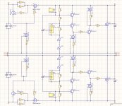
PS after looking at the schematic I am sure you intended IRF630. Now I am not so sure. Is the schematic in guide backwards for positive and negative voltage?
I read an earlier post from a fellow who wanted to use it with Rothacher's amplifier and you did not faint so I think I will give it a try!
First to check which mosfet I have in place ... I do have the IRF530.
Thanks YET again. Take care,
PS after looking at the schematic I am sure you intended IRF630. Now I am not so sure. Is the schematic in guide backwards for positive and negative voltage?
Last edited:

There are two .png UBiB schematic files in post #1. One has pos and another has neg in the filename. Polarity is also written inside the schematics when opened.First to check which mosfet I have in place ... I do have the IRF530.
Thanks YET again. Take care,
PS after looking at the schematic I am sure you intended IRF630. Now I am not so sure. Is the schematic in guide backwards for positive and negative voltage?
In a positive polarity UBiB, IRF530 is for M2 NMOS. Don't change that on chance because its influential for phase margin etc. M1 is PMOS. That's the CCS Mosfet. More powerful M1 types are not disruptive, just slower responding, and we want to choose those of not much intrinsic pF spec. The IRF9630 is fast enough for a 4A DC rated part.
Chances are you also have the IRF9530 meant for M2 PMOS in the negative polarity UBiB. This can work for M1 in the positive polarity albeit 8A DC rated, thus slower than the IRF9630. At least temporarily.
Sorry, Salas,
When in a state of enthusiasm I look at everything backwards. What an idiot. Looking at M2 when I needed to look at M1.
Sorry to have bothered you but grateful for the gentle correction.
Thanks and take care,
When in a state of enthusiasm I look at everything backwards. What an idiot. Looking at M2 when I needed to look at M1.
Sorry to have bothered you but grateful for the gentle correction.
Thanks and take care,
Hello,
I have a UGS muse preamp that I use with some Salas SSLV1.3 UltraBiB regulators and the sound coming out is very nice. The pcbs for the regs were drawn by a member for the group buy.
Each channel of the preamp draws 150ma per rail at 28V thus I set the ccs for 250ma leaving 100ma spare for the shunt. I have also 6v that I drop on each ccs. All this sums up as a lot of heat and big heatsinks are required. The preamp will be hosted in the next future in a modushop 2u enclosure that is entirely in aluminium. Each side panel of the enclosure has 2 cuts, as long as the panel is, having 45mm between them.
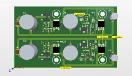
I thought to use the side panels as heatsinks and to mount the regulators directly on them.
Now I have 2 possibilities, one is to use a classic fr4 pcb and through hole mosfets or use an aluminium pcb and smd to-252 mosfets. The second option seemed more interesting to build and I started drawing a pcb but I came to a point that I want to ask for some help.
What smd to252 mosfets do you think would be best suited for this? Any other components that you suggest replacing?
Where is better to join the gnd, on the preamp pcb or on the reg pcb?
I have a UGS muse preamp that I use with some Salas SSLV1.3 UltraBiB regulators and the sound coming out is very nice. The pcbs for the regs were drawn by a member for the group buy.
Each channel of the preamp draws 150ma per rail at 28V thus I set the ccs for 250ma leaving 100ma spare for the shunt. I have also 6v that I drop on each ccs. All this sums up as a lot of heat and big heatsinks are required. The preamp will be hosted in the next future in a modushop 2u enclosure that is entirely in aluminium. Each side panel of the enclosure has 2 cuts, as long as the panel is, having 45mm between them.
I thought to use the side panels as heatsinks and to mount the regulators directly on them.
Now I have 2 possibilities, one is to use a classic fr4 pcb and through hole mosfets or use an aluminium pcb and smd to-252 mosfets. The second option seemed more interesting to build and I started drawing a pcb but I came to a point that I want to ask for some help.
What smd to252 mosfets do you think would be best suited for this? Any other components that you suggest replacing?
Where is better to join the gnd, on the preamp pcb or on the reg pcb?
Attachments
Hi, if it was me I would go for the first option since the GB layout and BOM's through hole Mosfets are a tried and tested combo. If you will go for the 2nd option, I can't tell about what SMD TO-252 more than try to select close gfs, Ciss, Crss, to the original TH types specs. Which differ for M1 and M2. Better to join the ground at the reg PCB since its not a Kelvin output.
- Home
- Amplifiers
- Power Supplies
- Salas SSLV1.3 UltraBiB shunt regulator