You are welcome. BTW your smd BC & 2SK choices should work. Your IRFR smd type for M1 also. But for M2 it may bring instability or not too good Zo. Find something closer to the IRF530/9530 spec there.
I have the regs from the GB(ugs muse)and use the same components as what I want to use now except the mosfets which are 610/9610.You are welcome. BTW your smd BC & 2SK choices should work. Your IRFR smd type for M1 also. But for M2 it may bring instability or not too good Zo. Find something closer to the IRF530/9530 spec there.
I will try to search for a better candidate for M2.
When searching for the actual mosfets I took as a reference the fqp3n30/fqp3p20 pair.
Good luck but do test for oscillation free rails when ready. With each layout difference there has to be verification.
You look for a clean horizontal line when scoping AC coupled at 5mV vertical through various horizontal scan speeds.
Use the short ground return coil style wire accessory on the probe's nose and 20MHz bandwidth limit.
You look for a clean horizontal line when scoping AC coupled at 5mV vertical through various horizontal scan speeds.
Use the short ground return coil style wire accessory on the probe's nose and 20MHz bandwidth limit.
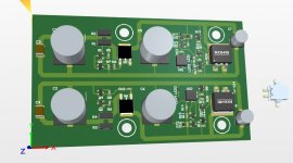
These small aluminum pcbs aren’t expensive, at most I can try a few pcb revisions if needed. I am also curious about how the pcb can handle the heat transfer.
When ready I do intend to share the gerbers if there is no problem with you.
When ready I do intend to share the gerbers if there is no problem with you.
Hi,
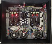
@Salas, what a sound upgrade by making separate power supplies for L&R channel plus the volume control.
BA3 preamp benefits from that a lot. Cheers.
@Salas, what a sound upgrade by making separate power supplies for L&R channel plus the volume control.
BA3 preamp benefits from that a lot. Cheers.
Attachments
Last edited:

Hi!
I have a few r core trafos , but all center tapped. I remember to read somewhere in the thread that there might be a way to use them in the ultrabib. Is this true or am I just imagining things?
I have a few r core trafos , but all center tapped. I remember to read somewhere in the thread that there might be a way to use them in the ultrabib. Is this true or am I just imagining things?
It takes to skip the board's rectification section and make a different diodes external bridge arrangement for center tapped symmetrical.
I have two questions... 60mA margin for M2 is ok? for a 40mA consumer.
What AC power is usually required? 300mA/ac for a total consumption of 100mA/dc, is ok?
What AC power is usually required? 300mA/ac for a total consumption of 100mA/dc, is ok?
Yes 60mA margin is OK. If the 40mA consumer is relatively steady and does not create sudden high demand peaks.
AC power source loses enough of its nominal mA after bridge rectification but 300mA AC still OK for 100mA DC circuit.
AC power source loses enough of its nominal mA after bridge rectification but 300mA AC still OK for 100mA DC circuit.
So, it will be something like this, right?It takes to skip the board's rectification section and make a different diodes external bridge arrangement for center tapped symmetrical.
Yes like that, i.e. classic arrangement as seen in symmetrical rails power amplifiers with a center tapped Tx and a diodes bridge
Ok Salas, thanks for your patience 👍. I'm going to try to make a board for it. Fingers crossed...

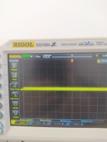
Its kinda thick line. Use the 20MHz BW limit in the channel 1 menu too and the short ground coil on the probe's tip. Anyway, about excess noise due to bench practice or not, a quick test to know is if it will change enough if you will power off the device under test. Without changing anything else in the test setup.
As an aside it needs to be mentioned that any offset in the scope's input amplifier will add to the RMS reading. Unimportant in normal oscilloscope work but disorienting when interested in the uV region. Standard deviation stat tells the truth in this case.
How Standard Deviation Relates to Root-Mean-Square Values
How Standard Deviation Relates to Root-Mean-Square Values
- Home
- Amplifiers
- Power Supplies
- Salas SSLV1.3 UltraBiB shunt regulator