Hello,
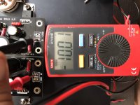
I did set everything up. LEDs were on, and I set the Voltage with a dummy load. Good to go.
When I connect the grounds of positive and negative rails, light goes off, no more than a view millivolts left.
I do have two separate windings on my transformer.
Any Idea?
I did set everything up. LEDs were on, and I set the Voltage with a dummy load. Good to go.
When I connect the grounds of positive and negative rails, light goes off, no more than a view millivolts left.
I do have two separate windings on my transformer.
Any Idea?
Hello,
I did set everything up. LEDs were on, and I set the Voltage with a dummy load. Good to go.
When I connect the grounds of positive and negative rails, light goes off, no more than a view millivolts left.
I do have two separate windings on my transformer.
Any Idea?
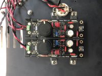
Post a picture so we can see your setup.
As you know there should not be a problem connecting output grounds together, maybe post photographs where we can see the AC inputs area and the rest.
Ok, it turns out, labelling of pos. neg. rail, and of 0, VDC is completely upside down.
Attachments
Last edited:
Make sure the MOSFET insulation is good on each one. What is the extra cabling to the negative's AC input?
Make sure the MOSFET insulation is good on each one. What is the extra cabling to the negative's AC input?
I did use these plastic things under the MOSFETs
The other cable is going to one more SSLV but at this moment not connected.
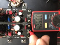
But did you use nylon grommets insulating the screws necks from the MOSFET tabs too? You can check if any continuity from tabs to chassis with the DMM. There should not be any.
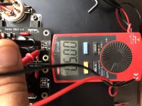
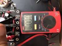
When all is well, in your last picture the DC indication from output points 0 to 0 should read 0.
I use plastic 3mm screws for fets and I still have problems once in awhile in getting them insulated. As Salas said, measure fets to ground. Let us know what it is.
The other cable is going to one more SSLV but at this moment not connected.
Sharing a secondary might give you problems too when connected
I use plastic 3mm screws for fets and I still have problems once in awhile in getting them insulated. As Salas said, measure fets to ground. Let us know what it is.
Continuity test from MOSFET tabs to some exposed chassis point (a large part's mounting screw or something) should show. Having DC between the zero output points is a fault. The current limiters saved the regulators when he wired them common and powered them up as they went down to mV outputs and dark.
Long live plastic screws!
Thank you very much!!!!!!!!!
You see

Victory photo please 😀
Sharing a secondary might give you problems too when connected
So using one trafo for two reg is a no go? I'm planning to use this with DCG3.
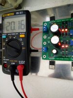
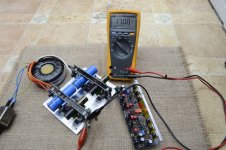
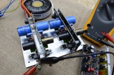
Here is my Ultra BIB power supply, working just fine from first power. Without touching the pot, each board was already at around 15.5V DC output, a few turns to get 17V was all that was needed.
Regs tested with 120R 5W loads. They take a while to settle to 17V so need to set at around 17.25 at start.
Will have a look with the picoscope later and connect to the DCG3.
Regs tested with 120R 5W loads. They take a while to settle to 17V so need to set at around 17.25 at start.
Will have a look with the picoscope later and connect to the DCG3.
Attachments
Here is my Ultra BIB power supply, working just fine from first power. Without touching the pot, each board was already at around 15.5V DC output, a few turns to get 17V was all that was needed.
Regs tested with 120R 5W loads. They take a while to settle to 17V so need to set at around 17.25 at start.
Will have a look with the picoscope later and connect to the DCG3.
YouTube
Without touching the pot, each board was already at around 15.5V DC output, a few turns to get 17V was all that was needed.
Is it a 10k trimmer?
- Home
- Amplifiers
- Power Supplies
- Salas SSLV1.3 UltraBiB shunt regulator