Salas please lets me know, that would be Ok. 18V ac on transformer, to get 17v dc. ?
that's to power a DCB-03 using dual mono Ubib.
that's to power a DCB-03 using dual mono Ubib.
Hi Salas
First of all congrats on the new upgraded design that I will build soon.
Now, as you know I like to understand the circuits I build and usually you take the time to write a description of the functions of the various components in your designs. Would you care to do the same here ?
I am particularly puzzled with the norton vref that seems to be working without a dedicated CCS as in the other versions.
Why did you choose to cascade Q3 with Q2 ?
Best
Ricardo
I reduced the current source to inherent Vbe/R (Q2,R5) because missing in-production low pinch off low noise high output conductance JFET to nest under one Vbe. Inherent also is the Vbe's negative thermal drift until warmed up. On the other hand yet another active noise source has been eliminated. You could put back one though if you must use a Zener instead of VRR when deleting VR1 (Vout=Vz+4.7V). That would solve the warm up drift if its crucial not to have it in some application. But better avoided if not a must. Also mentioned in the guide.
The rest of circuitry goes on same principles as you know in the SSLV series. In this iteration its a Vbe controlled MOSFET current source and a CFP (BJT+MOS) current shunt with the unity gain passive Vref we discussed sandwiched in-between.
The rest of circuitry goes on same principles as you know in the SSLV series. In this iteration its a Vbe controlled MOSFET current source and a CFP (BJT+MOS) current shunt with the unity gain passive Vref we discussed sandwiched in-between.
Hi,
I am aiming for 7v and -3v output for my hagerman phono. Can I use a Panasonic 6800uF , 30v that I already have for C1 or does it have to be a 50v ?
Thanks
I am aiming for 7v and -3v output for my hagerman phono. Can I use a Panasonic 6800uF , 30v that I already have for C1 or does it have to be a 50v ?
Thanks
Looking at schemantic on build guide, I think it's a mistake:
''For CC <1A M1 IRF9610...''
Instead of less ''<'', does should not be more ''>''?
''For CC <1A M1 IRF9610...''
Instead of less ''<'', does should not be more ''>''?
Hi,
I am aiming for 7v and -3v output for my hagerman phono. Can I use a Panasonic 6800uF , 30v that I already have for C1 or does it have to be a 50v ?
Thanks
You can use a lower voltage capacitor for C1. However, I think 5V is the minimal output voltage so you cannot do -3V...
You can use a lower voltage capacitor for C1. However, I think 5V is the minimal output voltage so you cannot do -3V...
I was under the impression it was symmetrical on the negative board and if necessary to use an LDO as in my application (Hagerman piccolo mc step up) it wouldn’t detract too much from the lower noise levels because it was on the negative rail.


Looking at schemantic on build guide, I think it's a mistake:
''For CC <1A M1 IRF9610...''
Instead of less ''<'', does should not be more ''>''?
The IRF9610/610 at M1 position are trusty enough as alternatives to the listed Fairchilds for below 1A constant current at about 5V across them. Still their core to case thermal resistance is significantly higher and their positive/negative type curves are not as close but they develop less VGS voltage while being easier to find and as fast or little faster for parasitic capacitance.
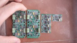
Here is my little power station... 3,3V x2, 5V x2 , 10V x2. All grounds only meet at the obscure object of desire!
Very nice

I was under the impression it was symmetrical on the negative board and if necessary to use an LDO as in my application (Hagerman piccolo mc step up) it wouldn’t detract too much from the lower noise levels because it was on the negative rail.
The negative 1.3 reg section can go down to around -5V DC output
Congratulations for this new reg. Salas, thanks for share and help.
I was confused, excited to find out, I read this thread on one sitting.
Now I learned that there are TWO substitutes for M1, for less than 1A. IRF9610. And then for high current, IRF9640. Ok. Ok.
Other than to power a DCB-03 preamplifier, and a 14v. Tripath chip amp., my plan is also use one UltraBiB as a prereg. set it at 7v. and then chain it to a several 500mA. modules ultralownoise 0.8mV. postregulators LT3405. These I got plenty and cheap on Taobao site. Are claimed a flexible voltage dropout between 1V. and 4V. So theoretically I could power many 3,3v and 5v. gizmos I have in my USB chain: Filters, hubs, memory sticks, clocks, etc.
Attachments
- Home
- Amplifiers
- Power Supplies
- Salas SSLV1.3 UltraBiB shunt regulator