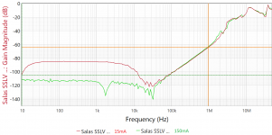
Some PSRR tests == without C1 (6.8mF). Board is cleaned of excess flux etc., etc. Powered by two 12V SLA batteries. Perturbation signal +3dBm
Attachments
Last edited:

Nice practical results I would think. ~Flat PSRR at around -120dB across the audio band and staying below -100dB at 100kHz. LT3045 "ultrahigh PSRR" linear reg chip has -85dB at 20kHz and -78dB at 100kHz in its datasheet I now see. LT1083 has -48dB and -30dB at those frequencies. But why skip C1? OK batteries have been used in this test, still it has an HF filtering role in combination with the Rf resistor and a local decoupling role to the CCS area layout as well. With nothing there this CCS may even oscillate on enough incoming wires inductance. At least a small decoupling capacitor is recommended in C1's place when the DC source is external. Like the CD cap in Reflektor-D when the DCin mode is used. Ref-D has a similar design main CCS.
Attachments
Nobody will blame you. Its a good choice especially in high CC 🙂
The guide's list has "For CC >1A C1 10000uF/50V". Of course you may use a lower voltage cap if not interested in high range Vout settings given that the trafo's secondary level is within your C1's voltage rating after rectified to DC.
The guide's list has "For CC >1A C1 10000uF/50V". Of course you may use a lower voltage cap if not interested in high range Vout settings given that the trafo's secondary level is within your C1's voltage rating after rectified to DC.
But why skip C1?
Because the line injector isn't happy with a capacitative load.
Is that the Bode 100 vector network analyzer by the way? Your charts remind me of some videos I have seen with that test machine.
As the beloved SSLV1.1 BiB shunt reg was getting long in the tooth especially for NOS JFETS I had in mind for some time now to design its successor. The goals were: 1. In production parts 2. Much simpler to set up. 3. Better technical and subjective performance.
After many breadboard experiments and two prototype PCB iterations I feel that my goals were finally met. So here comes the UltraBiB 😀
-Uses no NOS parts.
-Can do 5V to 40V output without changing a thing in its parts configuration.
-Nothing to choose and match. No tolerances in predicting its CCS limit setting.
-Has 45dB more open loop gain and many times less output impedance than 1.1
-Sounds easily better.
-Its an electrically and mechanically drop in replacement for an upgrade.
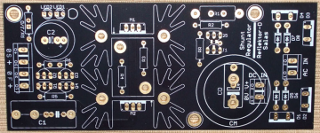
I have already given spare earlier proto boards with now deleted experimental features to few local beta testers. They are all happy by now as far as I know. The pictured board in green is the final layout in just cheapo proto that's a pain to rework and its pads vaporize in the end. It will come in proper grade black solder mask and immersion gold three sections board just like the original.
Attached: Zout plot for 150ma spare current and noise plots for 100,150,220,330,470,1000uF C2 (red 220uF). Also the rails probed on the scope for positive and negative sections. Here are typical values schematics also. I will write a PDF with instructions. Not that there is something truly special to consider when building it with the suggested parts but to describe it better as an item and to clarify details and precautions.
Updates:
31/5/18 R9's value update
1/6/18 OL sim at 100mA spare
2/6/18 Build Guide PDF added (0V0b)
I have few doubts in the new version compared to 1.1 :
1. There are also Jfets in the oder version compared to the new so can we use PF5102 instead of 2sk170? with adding 270ohm resistor instead of 10ohm restor in place of R4?
2. 2mv of noise is visible on the scope if im not wrong. So is that the best that can be expected from the regulator? is this value coming from the environmental interfered broadband noise or 2mv as on the scope output to be expected?
1. You can't use PF5102 instead of 2SK117 in the 1.1 with good results in the crucial Q103 (203 303) position for sure. In other positions you may but I don't know how the OLG will be affected. You should scale any degeneration resistors by test between types so to run the same mA in the JFETs again.
2. No, 2mV vertical is the setting i.e. each graticule is 2mV tall. An 8 bit scope can do as much. Also that's across 20ΜΗΖ bandwidth, noise amasses. Its an indicative capture I posted for stability and general check reference. Probe other regs to it and see. For uV/nV level noise analysis with curves, only Jack has both the 1.3 and the right gear around here. If he will ever test for output noise we will see.
2. No, 2mV vertical is the setting i.e. each graticule is 2mV tall. An 8 bit scope can do as much. Also that's across 20ΜΗΖ bandwidth, noise amasses. Its an indicative capture I posted for stability and general check reference. Probe other regs to it and see. For uV/nV level noise analysis with curves, only Jack has both the 1.3 and the right gear around here. If he will ever test for output noise we will see.
1. You can't use PF5102 instead of 2SK117 in the 1.1 with good results in the crucial Q103 (203 303) position for sure. In other positions you may but I don't know how the OLG will be affected. You should scale any degeneration resistors by test between types so to run the same mA in the JFETs again.
2. No, 2mV vertical is the setting i.e. each graticule is 2mV tall. An 8 bit scope can do as much. Also that's across 20ΜΗΖ bandwidth, noise amasses. Its an indicative capture I posted for stability and general check reference. Probe other regs to it and see. For uV/nV level noise analysis with curves, only Jack has both the 1.3 and the right gear around here. If he will ever test for output noise we will see.
Thank you for the reply Salas. Btw which hardware is required to test and analyze the curves for uV/nV level noises in audio band.
Audio Precision station on differential mode as main gear and a bunch of lab paraphernalia I would think but I am not an expert
I bought 100 of pf5102 from mouser through a dealer, they sent me a pack foil bag with pf5102 label but the inside are j111 in it.
After contacting with the dealer they said mouser reply that they are the same and the datasheet confirm it. The data sheet read "see j111 for characteristic". What do you think? Is it the same? I'm going to try it out anyway since they refuse the exchange.
Thank
After contacting with the dealer they said mouser reply that they are the same and the datasheet confirm it. The data sheet read "see j111 for characteristic". What do you think? Is it the same? I'm going to try it out anyway since they refuse the exchange.
Thank
Mouser has 10,210 pcs PF5102 stocked ready to ship as we speak. 5,252 pcs named J111 also. So they are differentiated by type and quantity as listed. J111 has -3 to -10V VGS(OFF) and 20mA minimum IDSS when PF5102 has -0.7V to -1.6V VGS(OFF) and 4 to 20mA max IDSS. Those figures are what I read in their datasheets attached by Mouser. I don't see how they are equal at all.
My 30pcs PF5102 samples (bought from Banzai Germany) had 5mA to 10.5mA IDSS and -1V VGS(OFF) at 7.5mA IDSS.
My 30pcs PF5102 samples (bought from Banzai Germany) had 5mA to 10.5mA IDSS and -1V VGS(OFF) at 7.5mA IDSS.
Mouser has 10,210 pcs PF5102 stocked ready to ship as we speak. 5,252 pcs named J111 also. So they are differentiated by type and quantity as listed. J111 has -3 to -10V VGS(OFF) and 20mA minimum IDSS when PF5102 has -0.7V to -1.6V VGS(OFF) and 4 to 20mA max IDSS. Those figures are what I read in their datasheets attached by Mouser. I don't see how they are equal at all.
My 30pcs PF5102 samples (bought from Banzai Germany) had 5mA to 10.5mA IDSS and -1V VGS(OFF) at 7.5mA IDSS.
That is what I don't understand, they have plenty of them but they send me something else.
I bought 100 of pf5102 from mouser through a dealer, they sent me a pack foil bag with pf5102 label but the inside are j111 in it.
After contacting with the dealer they said mouser reply that they are the same and the datasheet confirm it. The data sheet read "see j111 for characteristic". What do you think? Is it the same? I'm going to try it out anyway since they refuse the exchange.
Thank
This doesn't sound like something Mouser would say at all in my opinion.
When they screw up, the own it. They fix issues like this if they sent the wrong product to you.
That is what I don't understand, they have plenty of them but they send me something else.
That's some mistake or a policy I can't guess for what. Nobody sends something labeled with another code than what's printed on the package and expects it to be accepted by the customer even if its exactly the same. At least when not clearly listed as the same on their website.
Anyway measure IDSS and VGS(OFF). Beyond my findings in 30 pcs PF5102 I see there's a shop with some statistical data now that I look around for you and they are more or less agreeing: PF5102 N-channel JFET - Stompville Shop
But for J113 much stronger: J113 Matched Pair
Imagine for J111 which is the strongest...
Thank Salas, I just make a case and appeal to them directly, see what they have to say.
- Home
- Amplifiers
- Power Supplies
- Salas SSLV1.3 UltraBiB shunt regulator