Red or Green Wp2773 Leds for my ba-3 ?
At last, I have all the parts for my Salas 1.3 PS build. I ordered both of these leds, forgot why, but would like to know for sure which ones to use for the ba-3 lines stage, +/- /24v.... thank
At last, I have all the parts for my Salas 1.3 PS build. I ordered both of these leds, forgot why, but would like to know for sure which ones to use for the ba-3 lines stage, +/- /24v.... thank
Either. They only play a role for the lowest output voltage the reg can reach circa 5V. Reds have lower Vf and guarantee 5V or little under. Your application is way away higher from that area. Just use your favorite color between them two.
Salas your patience and support is legendary, fair play man.
Sorry if this has been mentioned, I'm dizzy researching threads... when using the BIB 1.3 with the DCG3, would omitting the C6 & C7 100uf supply decoupling caps on the DCG3 be a good idea?
Does the BIB like to see any capacitance on the output? The leads will be quite short for the build I imagine.
Sorry if this has been mentioned, I'm dizzy researching threads... when using the BIB 1.3 with the DCG3, would omitting the C6 & C7 100uf supply decoupling caps on the DCG3 be a good idea?
Does the BIB like to see any capacitance on the output? The leads will be quite short for the build I imagine.
Not sure if that would be a good idea because those are not only decoupling but also the DCG3's local reservoirs to its output MOSFETS. It may work without them in well dressed tight enough system builds but you got to confirm with an oscilloscope that the rails have no oscillations i.e. no distinctly periodic AC waveforms riding on the DC.
Then by ear decide what you prefer (with C6, C7, or without them). The 1.3 itself will not unsettle when there is at least few cm of cable and/or PCB track between it and further capacitors big or small. If you put them directly on its output connector it will react because they will drastically alter C3's characteristics.
Then by ear decide what you prefer (with C6, C7, or without them). The 1.3 itself will not unsettle when there is at least few cm of cable and/or PCB track between it and further capacitors big or small. If you put them directly on its output connector it will react because they will drastically alter C3's characteristics.

Diodes D1-D4
I like to construct this to power a Project RS Phono. The brick power supply specifies 18V 300mA output therefore according to the CC formula I need 400mA CC.
Due to space constraints, can I get away using MUR120 for D1-D4 diodes, if not are heat sinks necessary for MSRF860G.
I like to construct this to power a Project RS Phono. The brick power supply specifies 18V 300mA output therefore according to the CC formula I need 400mA CC.
Due to space constraints, can I get away using MUR120 for D1-D4 diodes, if not are heat sinks necessary for MSRF860G.
Use the MSRFs without sinks for 400mA CC. Although I would doubt that the Project phono actually pulls +/-300mA from its rails. That should be a maximum pull spec for driving very low impedance rail to rail because it has the LT1010 power buffer chips. If you can measure what it actually pulls when driving a normal line stage at maximum signal swing you could set the CC more realistically without excessive dissipation and sinking. That would help longevity of parts for sure and to reduce noise maybe a little.
Thanks Salas.
You're probably right that the Project does not actually consume 300mA, I'm just reading the spec on the power brick label. I'll try to measure the current as you suggest.
You're probably right that the Project does not actually consume 300mA, I'm just reading the spec on the power brick label. I'll try to measure the current as you suggest.
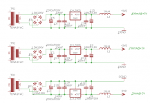
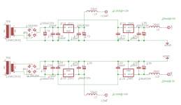
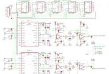
I tried to write total power dissipation of IC components which parts of PCM1704 DAC.Is SSLV1.3 UltraBiB ideal to change with these 78XX regulator circuits? For 5 different transformers with 7 UltraBiB are useful?..First regulator (400mA@+5VD) goes to USB/I2S conveter board.
Best Regards
Best Regards
Attachments
Last edited:
The +/-15V part is a nice candidate for Ubib, its for the analog output section. Maybe the third Ubib from its breakable PCB for the USB/I2S. 7 Ubibs would take too much real estate. Mini Reflektors for the rest if insisting shunt or replacement 7805/7905 better chips/3 pin discrete compacts from ebay etc. And a custom order trafo with many secondaries for everything. Better don't tap on the +/-15V for the 30mA +/-5V as shown. Use secondaries and bridges+reservoir caps of their own.
These are great quality boards, excellent job all round guys.
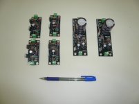
Looking at ways to minimise the footprint of four BIB's for the DCG3. Having them on edge means they will match the 160mm width of the amp board. All four will be mounted to a 4mm thick 130 x 160mm plate then to the chassis.
Trying a few left over BYW32 200V 2A rectifiers in these, they are very good diodes.
Attachments

Nice configuration idea
agreed, This has got my mind churning for a science project.
agreed, This has got my mind churning for a science project.
You could get down to 5mm spacers between boards and with 30mm res caps the total width of the assembly will be 68.2mm
BTW the layout provision for C2 & C3 not to obstruct a long tool's access to the M2's mounting screw comes to its own especially for this configuration.
Two BIBs and four Reflektor-D. Add four rectifiers/reservoir caps for the Reflektors and adequate heatsink. Let alone six secondaries, hopefully from three transformers.😱 It's going to be a big box!
Good luck with your complex build, and keep us posted
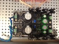
Finished assembly, no-load test... Nothing...Nada... Not working!
Even the LED's do not light up!
Data: This ps is for my ba-3 linestage, which I built with a Twisted Pear audio bipolar ps. So, the transformer is a toroidal 20-20 100va. Input voltage in the board is 20.6v
R1 3.3 ohm which was suggested by Salas.
The mosfets are as per BOM as specified for CC less than 1A
Also the regulators.
Checked and doubled checked solder joints and transistor labels to make sure they were positioned correctly, and it looks like they are. The jp.. transistors
are as per BOM.
The LED's are as per BOM, but I used the green ones and were positioned according to the A and K labels in the board.
And it is the same for both positive and negative boards. Obviously did something wrong. I'll check the led orientation again....Photo included.
Any suggestions will be appreciated. Thank you.
Attachments
- Home
- Amplifiers
- Power Supplies
- Salas SSLV1.3 UltraBiB shunt regulator