I use 4 salas ultrabib for +/-24V for my UGS muse preamp.
I would like the salas regulators to be power on when the preamp turned on or when coming trigger input signal, and to be power off in standby mode.
I don't like that when the preamplifier is in standby mode it gives heat continuously 24/7.
I don't want to disconnect the transformers (I use them and for others psu) or large charging currents before the capacitors.
Does anyone see a problem with low power latching relays to switch M1 transistor (Q3, IRF9610 on schematic) to OFF state ?
Simulations with Multisim show no problem.
Attachments
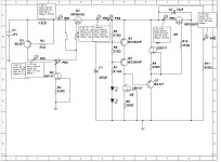
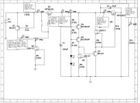
Theoretically its OK to short M1's Vgs cutting off the current source as control. Better test to see practical aspects of it like if transients are created during the switch that can threaten the gate junction or any form of oscillation. So to know what to expect or solve before integrating the idea into some expensive project.

Temperature drift on my regulator:
--------------------------------------
Time between measurements 1 hour.
Vdc(T1)=24.68V
T1(air)=22°C
T1(Q2)=22°C
T1(M1)=22°C
T1(M2)=22°C
Vdc(T2)=24.01V
T2(air)=27°C
T2(Q2)=34°C
T2(M1)=38°C
T2(M2)=40°C
ΔT(Q2)=34-22=12°C (Is it correct to measure the temperature difference here?)
ΔVdc=24.68-24.01=0.67V
Total temperature coefficient of regulator: ~ 55.8mV/°C
I don't have trimmers for Vref. Metal film resistors (1%, 50ppm) only.
I assume the high drift is caused by the LEDs (KINGBRIGHT L-934ID).
Is this so?
But I chose them because of their lowest measured noise (from a one thread here).
Temperature drift with Vishay NTCLE100E3472JB0 4.7K B25/85 3977K across R5 (270R).
------------------------------------------------------------------------------------
Time between measurements 1 hour.
Vdc(T1)=25.95V
T1(air)=27°C
T1(NTC)=27°C
T1(Q2)=27°C
T1(M1)=27°C
T1(M2)=27°C
Vdc(T2)=25.89V
T2(air)=28°C
T2(NTC)=34°C
T2(Q2)=34°C
T2(M1)=39°C
T2(M2)=42°C
ΔT(Q2)=34-27=7°C
ΔVdc=25.95-25.89=0.06V
Total temperature coefficient of regulator with NTC: ~ 8.6mV/°C
When measuring the noise (with and without NTC) no visible differences are observed.
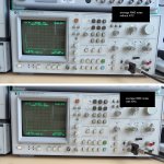
Analyzer settings:
-----------------------
PASSBAND SHAPE: FLAT TOP
AVERAGE: RMS
AVERAGE NUMBER: 64
--------------------------------------
Time between measurements 1 hour.
Vdc(T1)=24.68V
T1(air)=22°C
T1(Q2)=22°C
T1(M1)=22°C
T1(M2)=22°C
Vdc(T2)=24.01V
T2(air)=27°C
T2(Q2)=34°C
T2(M1)=38°C
T2(M2)=40°C
ΔT(Q2)=34-22=12°C (Is it correct to measure the temperature difference here?)
ΔVdc=24.68-24.01=0.67V
Total temperature coefficient of regulator: ~ 55.8mV/°C
I don't have trimmers for Vref. Metal film resistors (1%, 50ppm) only.
I assume the high drift is caused by the LEDs (KINGBRIGHT L-934ID).
Is this so?
But I chose them because of their lowest measured noise (from a one thread here).
Temperature drift with Vishay NTCLE100E3472JB0 4.7K B25/85 3977K across R5 (270R).
------------------------------------------------------------------------------------
Time between measurements 1 hour.
Vdc(T1)=25.95V
T1(air)=27°C
T1(NTC)=27°C
T1(Q2)=27°C
T1(M1)=27°C
T1(M2)=27°C
Vdc(T2)=25.89V
T2(air)=28°C
T2(NTC)=34°C
T2(Q2)=34°C
T2(M1)=39°C
T2(M2)=42°C
ΔT(Q2)=34-27=7°C
ΔVdc=25.95-25.89=0.06V
Total temperature coefficient of regulator with NTC: ~ 8.6mV/°C
When measuring the noise (with and without NTC) no visible differences are observed.
Analyzer settings:
-----------------------
PASSBAND SHAPE: FLAT TOP
AVERAGE: RMS
AVERAGE NUMBER: 64
Attachments

Its mainly due to Q2's negative Vbe tc. Normal drift for this reg. Not dangerous because it shrinks output instead of climbing above target. Both your tc and very low noise results are correct. Use of NTC resistor helps when you want no changes. I put R5 somewhere accessible in the layout. As Vbe applied over R5 lowers with temperature's rise the Iref drops. But the NTC resistance//R5 system drops Ω too and the Iref goes up again. You tuned your build right. 
Spelling error. I mean : of cource coefficients are negative...Off source coefficients are negative....sorry.
Yes. R5 is very comfortable to work with.I put R5 somewhere accessible in the layout.
If your target was 24V and you want to avoid a trimmer you must drop the value of the I-->V resistor now a little. Because NTC 4k7//R5<270R originally.
Yes it is.
I'll fine tune the Vout (24+0.2V) tomorrow.
Today I was surprised by the my drift, as in the UBiB guide I read about -7.5mV/°C.
I read your posts about Q2 in the thread. But I have over -50mV/°C. So I decided that the reason was in the others LEDs whitch I use.
I'll fine tune the Vout (24+0.2V) tomorrow.
Today I was surprised by the my drift, as in the UBiB guide I read about -7.5mV/°C.
I read your posts about Q2 in the thread. But I have over -50mV/°C. So I decided that the reason was in the others LEDs whitch I use.
-127.2 dBV over 25kHz is exactly 2.2nVrtHz as Tombo's findingWhen measuring the noise (with and without NTC) no visible differences are observed.
Analyzer settings:
-----------------------
PASSBAND SHAPE: FLAT TOP
AVERAGE: RMS
AVERAGE NUMBER: 64
That's Q2+Q3 Vbe + 2leds -Tc. Impact on Iref goes via the bias resistors V-->I translation. ΔVe/R=ΔΙR. Then multiplied by VR1's set value. Its a Norton ref.in the UBiB guide I read about -7.5mV/°C.
Now I understand.👍Then multiplied by VR1's set value. Its a Norton ref.
Only for info.
Vishay NTCLE100E3472JB0 4.7K B25/85 3977K is unsuitable !
At an ambient temperature of about 40 degrees and above, its tempco tends to dominate the tempco Q2 and the output voltage tends to slow increase.
gionag and Eric06 use NTC with B25/85 3590K. So look for those.
I dug through the my old stock from 30 years ago and found some 4K7 Russian thermistors (M4K7M) with unknown characteristics. They fit perfectly.
Attachments
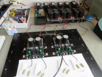
I realized that I have a number of BIB 1.3 boards "on the shelf".
In the future I plan to build the new Pearl3 Riaa (from Pass forum). For that build I plan to have the transformer / rectifier / CRCRC filter in a separate box.
On P3 board there are 7815 / 7915 regulators.
What would happen if I in PSU box implemented two BIB 1.3 -+18V DC power supply and used this very clean DC as input to the two P3 boards 7815/7915?
It should work?
I could not find information about using a regulated DC to feed another regulated DC (only serial connections of two serial regulators which is not the same as feeding it "as input").
UBiB has been used as external or internal pre-regulator for ready made or diy DAC units to good comment. The tight SMD components layout in such gear usually includes dedicated LDO reg chips next to main chips. So why not UBiB as pre-regulator for the Pearl 3 as well. Should work to good effect.
It could also be worthy to upgrade from 7815/7915 to those pin compatible little replacement boards with low noise low drop out LT3045 LT3094 SMD chips they sell on ebay etc. To take advantage of the quality pre-regulation better I suppose. A phono should best appreciate all low noise components in its rail chain.
It could also be worthy to upgrade from 7815/7915 to those pin compatible little replacement boards with low noise low drop out LT3045 LT3094 SMD chips they sell on ebay etc. To take advantage of the quality pre-regulation better I suppose. A phono should best appreciate all low noise components in its rail chain.
Also to mention that for UBiB as pre-regulator some negative thermal drift is not an issue since the end regulator fixes the nominal voltage rail. Just keep in mind to set the pre-reg's output voltage high enough not to ever drift below the end regulator's drop out spec. Safely high, not too high, avoiding to create unnecessary dissipation in the end (audio board's own) chip regulator(s).
Of course the current limit setting in the UBiB pre-reg should be set at about 100-150mA higher than the max current demand of the end regulator's load i.e the audio circuit that it feeds.
Of course the current limit setting in the UBiB pre-reg should be set at about 100-150mA higher than the max current demand of the end regulator's load i.e the audio circuit that it feeds.
- Home
- Amplifiers
- Power Supplies
- Salas SSLV1.3 UltraBiB shunt regulator