No sir; using an Antek 1222 with two pairs of blue/green outputs, one pair to each pos/neg board.
An over-current situation seems to be happening nonetheless. Are the bridge diodes inserted with the right orientation? See also if Q2 Q3 are good, if their junctions work with the DMM.
Agreed; I think the issue is my BA-3 board. Bibs work great when not loaded by it. The board also isn't biased yet so I'll use my DC power supply to work on that before reconnecting the Bibs. One set (+/-) ought to be enough to supply both sides of the BA-3, yes?
Stupid question/assumption check: Ground is ground, i.e. I can send the 0VDC outputs to ground along with the ground from the BA-3?
Thanks again for your help! I'm picking this project up after a couple of years and my notes got lost in a cross-country move.
Stupid question/assumption check: Ground is ground, i.e. I can send the 0VDC outputs to ground along with the ground from the BA-3?
Thanks again for your help! I'm picking this project up after a couple of years and my notes got lost in a cross-country move.
Working fine on their own eliminates suspicion you done something wrong in building them. It could even be their current limiting function is triggered when connected to your BA3. Measure how much current it draws with your test DC supply to see if you had set proper current limiting with R1 in the shunt regs. A shared +/- Ubib normally has the ability to cover two BA3 channels if the current limiting is properly set.
If your BA3 ground isn't a floating point no ground current will be created when attached to the shunts ground. Put their output grounds together and from there connect to the BA3 ground. Fuse that connection with a small mA value fast type to see if a big mistake is going on there.
If your BA3 ground isn't a floating point no ground current will be created when attached to the shunts ground. Put their output grounds together and from there connect to the BA3 ground. Fuse that connection with a small mA value fast type to see if a big mistake is going on there.
It can if you will use IRF630 and IRF9630 MOSFETs. Depending on Qutest's peak to average consumption pattern it may dissipate a lot of heat though. A shunt regulator like this has to be set idling at least 100mA above the max expected load current. Whatever reserve isn't asked by the load gets burned in the regulator. Runs most efficient on steady current loads. So you can set it idling close. Its like a high bias class A amplifier.

Hi
I am building the 5V shunt regulator. I’m using a 9 VAC toroid and Rs is .3 ohm to get a 2 amp output. On powering up the output is fixed at 12.65 VDC with no response to the VR1 pot. I substituted IRF 9630 for the FQP3P20 and IRF 630 for the IRF 530 as you suggested
Could you offer any advice?
Thanks
Mark
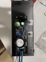
Attachments
If you have enough current test first wit a 2.5 ohms 30W dummy load the regulator.
Could you check or you know for sure the real load draws 2A?
Could you check or you know for sure the real load draws 2A?
It’s for a DAC the Qutest
Is R1 of .3 ohm correct?
I checked it without a load
Thank you
Mark
Is R1 of .3 ohm correct?
I checked it without a load
Thank you
Mark
Pls measure the voltage across R1 0.3 ohm, regulator don't need to be loadedIt’s for a DAC the Qutest
Is R1 of .3 ohm correct?
I checked it without a load
Thank you
Mark
- Home
- Amplifiers
- Power Supplies
- Salas SSLV1.3 UltraBiB shunt regulator