Yes, you are right. It still works fine now the dac board is repaired!

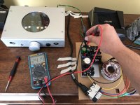
This is what Q3 look like in-circuit, without Q2 installed. No exactly “right”, but better than the 3 Ohm resistor that Q2 reads (out of circuit).
Should I go through the hassle of removing Q3 to measure it outside the circuit? Should I measure Vbe with the multimeter? Or is this good enough?
Thanks so much for all the support! It is highly appreciated and makes buying this kits even more compelling! Really thanks a lot!
Rafa.
You are welcome. No don't remove Q3 for now, Vbe looks good and that should be enough, don't expect a correct hfe reading in circuit. Have a go with just Q2 replaced and we will see.
Hi Salas, I think this is a long overdue Thank You. Your support is amazing, without it, no matter how good the designs are, we will not be able to fix the issues. Appreciate it.
P.S: I am happy I have no issues. 🙂
P.S: I am happy I have no issues. 🙂
I have a singing ACP+ with a linear PSU!!! Thank you.
Yes, replacing Q2 did the trick, nothing else needed changing. Unfortunately, I had to canibalice my yet-to-be-built bi-polar PSU that i will build with the other 2 PCBs and, as Murphy will have it, with the one obsolete and non stocked Transistor! LOL! I’ll order a few BC559B (not sure why is the B the replacement for the C) with my next Mouser order. I take it they are a direct replacement as long as Vout < 30V.
I still have a few things to sort out, my drift is quite considerable, about a full volt. So I need to ask if the ACP+ Can tolerate the extra voltage on startup or if i am better not overshooting and then living with a lower Vout.
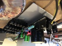
The other thing, and here I’d like some suggestions: I put individual heat sinks on the Ms, M1 is cooking at 80°C on the MOSFET metal next to the bolt. Heat sink is at 67°C, so there is good transmission of heat, perhaps a bit smaller than needed. M2 is a bit cooler at 68°C.
They are far from the operating range of 150°C, but this is with open case. So I may need to put a thick aluminum plate beneath the heat sinks. They are “floating” some 5mm above the base. Or is 80 reasonably enough?
I’m attaching some pics, more to say thanks! For what is worth, my “troubles” were of my own making and not at all a problem with the kit, which is superb!
Best,
Rafa.
Edit: damn iOS, that upside down photo was not like that! 🙁
Yes, replacing Q2 did the trick, nothing else needed changing. Unfortunately, I had to canibalice my yet-to-be-built bi-polar PSU that i will build with the other 2 PCBs and, as Murphy will have it, with the one obsolete and non stocked Transistor! LOL! I’ll order a few BC559B (not sure why is the B the replacement for the C) with my next Mouser order. I take it they are a direct replacement as long as Vout < 30V.
I still have a few things to sort out, my drift is quite considerable, about a full volt. So I need to ask if the ACP+ Can tolerate the extra voltage on startup or if i am better not overshooting and then living with a lower Vout.
The other thing, and here I’d like some suggestions: I put individual heat sinks on the Ms, M1 is cooking at 80°C on the MOSFET metal next to the bolt. Heat sink is at 67°C, so there is good transmission of heat, perhaps a bit smaller than needed. M2 is a bit cooler at 68°C.
They are far from the operating range of 150°C, but this is with open case. So I may need to put a thick aluminum plate beneath the heat sinks. They are “floating” some 5mm above the base. Or is 80 reasonably enough?
I’m attaching some pics, more to say thanks! For what is worth, my “troubles” were of my own making and not at all a problem with the kit, which is superb!
Best,
Rafa.
Edit: damn iOS, that upside down photo was not like that! 🙁
Attachments
Last edited:
Congratulations for fixing it. Your now sinks are surely tiny, definitely more substantial sinking is needed for your app. Higher temps are generally eating away electronics lifetime even when away from an imminent destruction limit. They possibly contribute to your now drift level as well. BC5xxB variation has less Hfe than C but still adequate. C was out of stock then. When C is stocked prefer C.
Rafa‘s issue made me worry a little about the heat-dissipation. I‘ll use mine for the BA3 preamp, 24V transformer (and the rest I must look up @ workshop)…
How do I calculate the heat-dissipation, to make sure I won’t cook anything but dinner?
Many thanks
d.)
How do I calculate the heat-dissipation, to make sure I won’t cook anything but dinner?
Many thanks
d.)
For me, this matches perfectly the behavior I saw. This math in my case:M1disW=(Vin-Vout)*Iccs
M2disW=Vout*(Iccs-Iload)
M1: 5W
M2: 3.2W
Perhaps for 24V I should have opted for a 22V secondaries transformer instead of the 24V one, but not sure if those are too common, the ones I could purchase in Mouser jumped from 18V to 24V, so that's it.
5W + 3.2W of dissipation for me, which gives me about 60° over ambient with those heatsinks. Yeah, I'll add more dissipation. I'll keep those, and bolt them to a large aluminum bar that would be heatsinked to the chassis itself. Let's see. Had I known this, I would have probably mounted them vertically and try to secure a "vertical" heatsink. As is, I will need to get creative.
Myleftear, you were the one that pointed me in this direction, how is it that I beat you to building this? 🙂 Good luck with your build.
Thanks again,
Rafa.
Last edited:
5VDC vin-vout at least is good to have. In your case that would give 0.577V/1.2R=0.48A. 5V*0.48A=2.4W. Why you burn 5W on M1? You have 34V rectified with that transfo?
Sorry, yeah, I copied something wrong apparently.
Still: 24V transformer. I did measure a little more RMS than that, but I'm sure that the rectified voltage after the diodes is 31V. Output is 24V. Iccs is, according to the PDF, 600 / R1: 500mA. You have a 'tighter' number on those .577V.
So: M1 W = (31V - 24V) * 0.5 = 3.5W
For sure, my M1 runs considerably hotter than M2, so for sure it has to be dissipating more than M2. I don't know. 3.5W makes more sense? I don't think its 2.4W, that would be much cooler, even according to the heatsink datasheets.
3.5W makes more sense. 24VAC Tx when including diode losses can give around 31VDC indeed. 7V in-out is good on M1 as it keeps its internal capacitance low enough. I used 0.577V to calculate Iccs because you mentioned 577mV drop across your R1 in a previous post.
Ah, I see where those .577V come from. That was the non-working PSU that couldn't go beyond 20V, if that makes any difference. I should probably re-measure that, unless R1 current is not affected by what was "not working" (lower Vout).
Still, I already have a heat dissipation that already gives 'acceptable' numbers, so anything better would be ideal, as long as I don't make it worse. So will try and source some aluminum and see what happens to design the case.
Thanks again so much.
Rafa.
Still, I already have a heat dissipation that already gives 'acceptable' numbers, so anything better would be ideal, as long as I don't make it worse. So will try and source some aluminum and see what happens to design the case.
Thanks again so much.
Rafa.
I believe you will make it significantly better. R1 drop probably wasn't affected even when Q2 was blown, but you can remeasure R1 drop now you fixed the reg to confirm. To be positively accurate when you calculate dissipation.
Oh, and, in your experience, does it merit to build the Quasimodo anti-ringing part?
I obviously would need to ring a lot. I take it I can build MJs "simple no math" quasimodo and determine the Rs. How do I determine Cs and Cx?
Thanks!
Edit: "I would need to READ a lot", not ring... that is what I am trying to avoid! 😛
Edit 2: I found Marks extensive paper explaining Cx and Cs. I will read that, maybe build the rig. Do you think it improves a lot the PSU?
Last edited:
Its good to populate the anti-ringing parts, they may smooth a psu+pre sound further, but not an urgency if they don't feel rather coarse sounding as they are. They start with Cx=10nF Cs=150nF on Quasimodo and vary 1k RV1 to find Rs I believe.
Yup, that's spot on.
I've snubbed many a psu based on quasimodo test, easy to see result on a scope, never been able to hear a difference though.
I've snubbed many a psu based on quasimodo test, easy to see result on a scope, never been able to hear a difference though.
I finished assembling eight Ubibs this afternoon (4 pos and 4 neg) for a preamp I am building. Every single one of them powered up and worked perfectly. Thanks Salas for a very robust design that works very well. They all stayed rock steady to the 10mv limit of my multimeter (in DC volts mode) as I varied load and input voltage. Impressive design!
And thanks Teabag for the high quality boards and build kits.
And thanks Teabag for the high quality boards and build kits.
- Home
- Amplifiers
- Power Supplies
- Salas SSLV1.3 UltraBiB shunt regulator