What raw DC do you measure across each C1's pins, and is it also showing correctly on the DMM for expected polarity? Your raw DC board is dual bridge so it normally gives two independent supplies. Detach the two extra black cables from the raw board's output connectors that go to the star bolt, for test. Maybe they stay at some potential ref to the other raw board. Better to common between the regs PCBs zero points in the end. Takes one short cable, that's better.
I'm an idiot... the polarity of the golden caps were wrong.
It's all good.
atleast for now, who knows what nonsense I'll bring next.
Thank you Salas for your help!
It's all good.
atleast for now, who knows what nonsense I'll bring next.
Thank you Salas for your help!
See their tops aren't domed even slightly and their value still measures in spec. In case they managed to pressure cook a little during wrong polarity applied. Discharge them with a hundred Ohm resistor until 0V before trying uF measurements.
the tops are slightly domed, i will replace them.
general question as you are very experienced.
Can you recommend something that I can use to learn and to look for mistakes? like books or tools
general question as you are very experienced.
Can you recommend something that I can use to learn and to look for mistakes? like books or tools
That 'bubbling sound' was probably your caps on the BIB brd getting 'cooked' as you mentioned - I have made same mistake myself unfortunately, and ended up with a mess. Hopefully, yours might have survived, as Salas mentioned - well worth a try.
I noticed that you have positioned the diode bridge on top of the raw supply KG caps - I once found one of the soldered component ends punctured the insulation of the similar KG caps and caused great confusion - a great frustrating/learning exercise!
If you haven't added extra protection layers between the caps and the diode board, you might look at this too ...
I mounted the pcb on long plastic 'standoffs' like one of those sea drilling platforms and used double sided tape to hold the caps to the base with enough clearance to be safe but still glued a sheet/layer of that black patterned tough plastic that's used in building industry as a moisture barrier at the bottom of brick walls - out here, it's a common material but anything tough will resist sharp points puncturing through.
There's also readily available double-sided adhesive thick plastic foam (used extensively in the car industry for badges, bumper strips, etc) that'll fasten the board to the caps and maintain enough space to ensure no contact - various methods 'outside the square', as they say.
Remember, making mistakes is pretty normal (everyone does it!) and a very quick way to learn.
Power supplies like these ones of Salas' can produce remarkable improvements to nearly any circuit - they're not cheap, not easy but extremely good.
All the best and "enjoy the diy learning"
Thank you very much!
It's nice to have help when you need it. Hope one day that I can give something back.
It's nice to have help when you need it. Hope one day that I can give something back.
Can you recommend something that I can use to learn and to look for mistakes?
Watch 12voltvids and Xraytonyb on YouTube. One is good in finding the fault fast and repairing it quick and dirty, the other one is good in demonstrating use of test gear and performing quality restorations. They explain as they investigate and repair so you learn practical stuff.

Good afternoon frieds!
I have a (hopefully) quick question. Im starting to build a V+ to use as a 24V linear PSU for the Amp Camp ACP+, which draws 370mA, constant current (being class A).
My options for R1 are:
1. 1R2 included with kit, which will give 500mA with a near-limit 130 extra mA
2. 1R3 5W yageo CEMENT Wirewound Resistor. This would be near ideal 90mA extra current to the 370mA drawn by PRE, but I am utterly unsure if cement wirewound would work as expected.
3. 1R5 5W Panasonic metal film resistor, which would give only around 30mA of extra current, which seems beneath the suggested 50mA point.
So, as you see, I have one option that is true and tested but would be wasting almost the full extra 150mA, one that would be “ideal” in terms of value but with doubts about the type of resistor, and one that would be a little beneath the 50mA minimum extra current required.
What should I do? Waste the extra current (with the degraded performance mentioned in the PDF), go with the Cement resistor, or risk being near the minimum limit?
Thanks so much!
Best regards,
Rafa.
What should I do?
Use the 1R2 because its a headphones amp and it may occasionally ask extra mA for peaks in 32Ω. Sometimes there is also less than 0.6V Vbe impressed on Ubib's R1 by Q1 samples tolerance. So somewhat less CCS in the end than the initial rough prediction anyway.
Hi,
One of my ultrabib pcb’s browned out last weekend due to a short circuit in an electrolytic in the pcb of my dac.
Before I break down the complete pcb; what is the usual suspect that is broken in such a accident?
One of my ultrabib pcb’s browned out last weekend due to a short circuit in an electrolytic in the pcb of my dac.
Before I break down the complete pcb; what is the usual suspect that is broken in such a accident?
It has an inbuilt constant current limiter so it could have been saved. Look first if Rf, R1, are not discolored and still reading nominal values. If those are OK the limiter and rectification probably still good. Voltage tests to do next is C1 has its expected raw DC, Vdrop across R1 legs is normal (0.55V-0.6V), between pins 1,3 of M1 Vgs is normal (4V-6V). At M2 1,3 pins about 4V is normal. If with too wrong Vgs replace the associated Mosfet. Lastly check that the voltage output is still normally adjustable.
Thanks, 1R2 it is then!Use the 1R2 because its a headphones amp and it may occasionally ask extra mA for peaks in 32Ω. Sometimes there is also less than 0.6V Vbe impressed on Ubib's R1 by Q1 samples tolerance. So somewhat less CCS in the end than the initial rough prediction anyway.
Good evening friends. I write saddened with a half-working PSU.
I'll write here the configuration, then behaviors before and after it started failing, then provide some voltages in the hope that someone could help me navigate and find the error.
Thanks so much in advance!!!
Config:
- 24V Toroidal Transformer 25VA
- R1: 1R2 as suggested in previous posts
- Target Voltage: 24V
- Original load (more on this later): 60 Ohms in 2 x paralleled 120 Ohm@5W
Behavior:
- When first started up, everything mostly worked, I moved the potentiometer rightwise and it reached the 24V I was aiming for.
- Did some initial measurements, things were mostly OK, load resistors were getting extremely hot, they are at the limit of their 5W range according to my calculations
Disaster:
- I decided to put my (new out of the box) oscilloscope probe to measure voltage drop on the load resistors (with the ground of the probe to v0, this may have shorted VDC 0 to earth ground if that could be an issue?) in order to use my multimeter as a thermometer (don't have two multimeters or other way to measure temps 🙁 )
- Here, the oscilloscope probe weight cased the jumper that was connecting the load to lift without me noticing, so the PSU went without a load for about a minute until I figured it out.
- Disconnected everything, but M1 to the touch was unbearably hot. I measured it cooling down from around 100°C or so 🙁
Behavior after disaster:
- Hooked back up the load, disconnected the oscilloscope, now I cannot go past 20.8V or so with the potentiometer all the way to the right.
Measured data AFTER disaster:
- AC input at terminal measures 26 VRMS between the two screws on the euroblock
Everything below are DC Voltages measured to ground:
- Rf: 31V (which looks like the diodes are rectifying correctly?)
- M1: S: 32V, D: 20.84V, G: 26.10V
- M2: S: 0V, D: 20.77V, G: 3.56V
Vout: 20.72V
Drop on R1: 577mV
Pot behavior:
- I turned the pot all the way to the left, turned on very briefly, measured output at 4V
- I turned the pot halfway (it appears to be a 30-turn pot) and it measures 14V at the output
- I turn the pot all the way up and I cannot go over 20.8V
So, what are my next steps? What other measurements could be useful / hint providing? What other steps could I take to start narrowing down the problematic parts? Who are the most likely candidates to have failed?
I'd appreciate any insight, and I would be grateful for all the patience, I am kind of a newb, even after a few years building DIY projects. They mostly have just worked (like this before I fried it somehow 🙁 ).
Thanks so much and sorry to bother you friends with my issues.
Best regards,
Rafa.
Edit: If you require further measurements, please describe the conditions: with or without load, different load, etc. Thanks.
Last edited:
During no load condition all constant current produced from M1 goes to ground through M2 only. M2 gets heat stressed because it dissipates W=Vout*Iccs without Iload share. If its an output short M1 gets all the stress (W=Vin*Iccs) because Vout=0V.
But in your measurements their Vgs still looks normal afterwards (M1 6V M2 3.56V). Thanks to set Iccs current limit M1 can't pass current up to the bridge diodes and transformer limit until something breaks.
First look if Q2 got hit and has wrong Vbe much away from 0.6V. If its too small it can't provide the Vref branch with enough current to reach 24V as it did before the mishap. Also look if Rf & R1 still read as their nominal values.
Thanks so much for the quick reply. Yes, Q2 appears to be fried... it reads as a 3 Ohm resistor in the part tester. The multimeter in diode testing mode reads 3.5v even between the "wrong" legs that should not allow current.
Would it be enough to replace Q2 and try again? Should I test if that fried something else?
Thanks so much.
Rafa.
Would it be enough to replace Q2 and try again? Should I test if that fried something else?
Thanks so much.
Rafa.
It has an inbuilt constant current limiter so it could have been saved. Look first if Rf, R1, are not discolored and still reading nominal values. If those are OK the limiter and rectification probably still good. Voltage tests to do next is C1 has its expected raw DC, Vdrop across R1 legs is normal (0.55V-0.6V), between pins 1,3 of M1 Vgs is normal (4V-6V). At M2 1,3 pins about 4V is normal. If with too wrong Vgs replace the associated Mosfet. Lastly check that the voltage output is still normally adjustable.
Yes, you are right. It still works fine now the dac board is repaired!
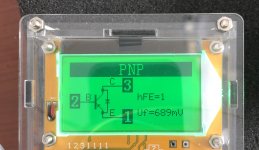
This is what Q3 look like in-circuit, without Q2 installed. No exactly “right”, but better than the 3 Ohm resistor that Q2 reads (out of circuit).
Should I go through the hassle of removing Q3 to measure it outside the circuit? Should I measure Vbe with the multimeter? Or is this good enough?
Thanks so much for all the support! It is highly appreciated and makes buying this kits even more compelling! Really thanks a lot!
Rafa.
Should I go through the hassle of removing Q3 to measure it outside the circuit? Should I measure Vbe with the multimeter? Or is this good enough?
Thanks so much for all the support! It is highly appreciated and makes buying this kits even more compelling! Really thanks a lot!
Rafa.
Attachments
- Home
- Amplifiers
- Power Supplies
- Salas SSLV1.3 UltraBiB shunt regulator