hi! will center tapped transformer with only 2 rectifier diodes be better? and will a CLC filter improve dirty ac power?
Full bridge as the board is, its better in this case. CLC filter is good if there is pollution in the mains. Else it can up the cost and primary side impedance without practical benefit. If you already got one such filter you may compare with and without it in your particular installation.
I have a hopefully quick question. I’ve built this regulator for +5V using a group buy kit with one of the transistors specially selected for +5V. Everything seems to be working. Now I need to change the output voltage to a higher value (somewhere between 6V and 8V). When I twist the pot, the output voltage increases. I also can take care of calculating the proper values of the input resistors and the pot. The input voltage will be sufficient.
My only question is, is this OK to do with this +5V-rated transistor in place? And if so, to what extent (e.g. is 8V OK?)? Or do I have to replace this transistor? Thanks for your insight!
My only question is, is this OK to do with this +5V-rated transistor in place? And if so, to what extent (e.g. is 8V OK?)? Or do I have to replace this transistor? Thanks for your insight!
The selected IDSS JFET for good performance at 5V output in this circuit is also good for any higher output voltage setting up to max spec. What is the new higher Vout application? Pre-reg? Analog stage of a DAC?
Thank you Salas! The higher voltage is just to test the sound quality difference from replacing SMPS for this device: ISO REGEN – UpTone Audio
Salas,
I'd like to use two separate chassis, one for the dual transformer UltraBIBB1.3 setup, and one for the Pete Millett Nutube preamp build. But I've been reminded by alexkosha that the umbilical between the two can't be too long. Can you please give me an educated guess about how long that would be?
Thanx
Performance wise its beneficial not to be long. Not that extra length will make the shunt regs oscillate or something. Keep it half a meter or under if practical. And with thick enough wires.
Best practice is to keep the shunt regs in the main box near the preamp pcb if there is space. The transformers can stay in another box, also rectify and filter there, just send raw DC to the shunt regs directly at their C1s. Not caring about umbilical length adding resistance and inductance. Because not used for carrying over the PSU outputs to their loads anymore.
Best practice is to keep the shunt regs in the main box near the preamp pcb if there is space. The transformers can stay in another box, also rectify and filter there, just send raw DC to the shunt regs directly at their C1s. Not caring about umbilical length adding resistance and inductance. Because not used for carrying over the PSU outputs to their loads anymore.
Pmus
hi i have a question will improve the sound of saligny bridge?
Like this
hi i have a question will improve the sound of saligny bridge?
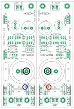
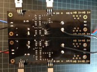
I think I found the problem.
After reading your questions myleftear, I checked everything again with schematics.
I connected Negative ground to the wrong side (not gnd).
thanks for questioning
After reading your questions myleftear, I checked everything again with schematics.
I connected Negative ground to the wrong side (not gnd).
thanks for questioning
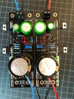
I rewired both ubibs and the led goes on on both.
But lightbulb tester tells me there is still a short somewhere.
The psu without ubibs connected works good.
Also can I easliy omit rf or should I look for a substitute, a more appropriate wattage for 34v in/24 out and 166ma?
But lightbulb tester tells me there is still a short somewhere.
The psu without ubibs connected works good.
Also can I easliy omit rf or should I look for a substitute, a more appropriate wattage for 34v in/24 out and 166ma?
Doesn't the bulb go dim after an initial flash (C1 inrush)? If not, see that M1(s) are insulated well and show Vgs too. You can omit Rf.
Lightbulb goes dim after initial flash but continues to glow. (40w bulb)
So I'm too scared to turn it on for longer than a few sec.
So I'm too scared to turn it on for longer than a few sec.
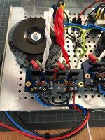
Yes correct when to jump each Rf going directly to each C1. How are the grounds common for dual reg? They already meet at the raw DC supply? First check all Mosfet tabs must not making contact with the chassis. Buzz them out utilizing the DMM's continuity test mode.
Even if I power it up not on the chassis it does not work.
The grounds are directly connected at raw dc nothing in bewteen.
Also it makes this sound as if something would cook, very concerning.
The grounds are directly connected at raw dc nothing in bewteen.
Also it makes this sound as if something would cook, very concerning.
Attachments

- Home
- Amplifiers
- Power Supplies
- Salas SSLV1.3 UltraBiB shunt regulator