I just moved all FET-s to the final position, and to minimize leg length, as close to the pcb as possible. Because earlier for the easy replaceability I soldered all FET with the original leg length.
Sorry for bothering.....just trying to power up for the first time....nothing at all......realised I've omitted Rf!
I have 0.05 non inductive 2w and also some cheap 0.1R 2w.
Are either acceptable in the Rf position? Just for testing purposes initially
I have 0.05 non inductive 2w and also some cheap 0.1R 2w.
Are either acceptable in the Rf position? Just for testing purposes initially
Top man for replying so fast as usual Salas thankyou
It works better with Rf fitted doesn't it!
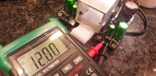
Success on first flick of the switch. 12v ac in for 12v out as a test. Will be for opamps in a dac so may use a 15vac for 12vdc out. I used 4r7 for R1 for 60ma load.
Screwed to an aluminium channel....see how that works.
It works better with Rf fitted doesn't it!
Success on first flick of the switch. 12v ac in for 12v out as a test. Will be for opamps in a dac so may use a 15vac for 12vdc out. I used 4r7 for R1 for 60ma load.
Screwed to an aluminium channel....see how that works.
Attachments
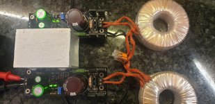
Weird indeed. Salvaged a couple meters of if out of uPVC window frame. 50mm sq.with 3.6mm thick walls.
16vdc rectified. Most of my 12v trafos come up 'hot but these are just about 13vac so a little lower than expected.
16vdc rectified. Most of my 12v trafos come up 'hot but these are just about 13vac so a little lower than expected.
Nice with the weird sink.
Would have been nice to orient the sink vertically so it acted like a heat tunnel.
But looks like it is a shade too narrow to bridge the two mosfets and you may not have had the height in the chassis.
Is it hot to the touch?
Rush
I could have just squeezed them on in the other orientation but would have meant drilling blind holes into the web of the adjacent side.
Mildly warm..25C measured with ambient 16C. Been on for one hour with no load so maybe I can afford to up the CCS.
I have a small 40mm fan but not looking necessary at the moment
Correction....R1 is 4r3.
Mildly warm..25C measured with ambient 16C. Been on for one hour with no load so maybe I can afford to up the CCS.
I have a small 40mm fan but not looking necessary at the moment
Correction....R1 is 4r3.
Last edited:
I had an idea of using a peltier module to power the fan at a low voltage once the heatsink warmed up. Assuming I could reach a big enough temp delta to work the thing!
Just a thought, someone looking to do this could cut them in half, bolt them together so the mosfets would be towards the center of each half and have the same area of heat sink, and have the heat tunnel effect.
Rush
Rush
So I was going to say that 4r3 isn't providing enough current for 2 opamps, which surprised me. Positive rail sagged to I think 5v and neg rail collapsed to as good as zilch.
This was with a pair of 1612s on dip adaptors in a dac but now I suspect them as faulty. I have used them before in an Ian Canada IV stage.
Tried a pair of vanilla 5532 (JRC 2114) and the rails are now good.
But......heatsinks are cold. Well they are 5C above ambient approx. And I have yet to load in the analogue pins of 2 x AD1862. So I shall lower R1 for more CCS
Salas, did you try 2N5457? LTSpice shows even better PSRR with it. I think I'll try when my PCBs arrive. Have them in my stock.
Yes I had. PF5102 isn't far from a 2N5457 in practice. Models in Spice may have differences like more Yfs.
But......heatsinks are cold. Well they are 5C above ambient approx. And I have yet to load in the analogue pins of 2 x AD1862. So I shall lower R1 for more CCS
Have spare current that gives +10C on ambient. Such a difference is well tolerated in builds.
This was with a pair of 1612s on dip adaptors in a dac but now I suspect them as faulty. I have used them before in an Ian Canada IV stage.
Tried a pair of vanilla 5532 (JRC 2114) and the rails are now good.
Current limit section is a good monitor beyond its isolation service. Saves from shorts and indicates problems. Just like a lab PSU.
Full disclosure now i have just learned I had the wrong op amps ...dual/single incompatibility. My beginner bad.
So probably the 4r3 is ok when the psu is asked to do the correct thing.!
So probably the 4r3 is ok when the psu is asked to do the correct thing.!
- Home
- Amplifiers
- Power Supplies
- Salas SSLV1.3 UltraBiB shunt regulator