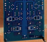
It's the negative board, positive pin of the cap.
Which voltage section's underside is that? The positive or the negative?
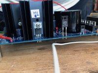
Mike hi, you are welcome. Nice that you liked it. Can it be you set rather much spare current for the job so M2 is the hotter spot? Maybe feasible to hold it back a little.
Hi Salas,
I honestly do not know how much current my streamer uses steady state. Its factory power supply is spec'ed at 1A, hence, I biased the Ultra using a 0.65 ohm resistor, which resulted in ~0.85A CCS.
M2 dissipates a full 15V* shunt current, hence, running ~10 deg C hotter than M1. M1 only dissipates 4*0.85, about 3.4W. M2 probably is 2X higher in wattage as it takes on 4X voltage.
As you said, I may need to cut back CCS to reduce the load on M2.
Mike
On the other hand it could be the Aries truly demands that much peak current at a point but irregularly. So M2 inevitably burns highish spare current whenever the Aries has to idle. Only true way to know the average and peak demand is to put the DMM between PSU & Aries in series as an Ameter and watch. If there is a min max function button even better.
On the other hand it could be the Aries truly demands that much peak current at a point but irregularly. So M2 inevitably burns highish spare current whenever the Aries has to idle. Only true way to know the average and peak demand is to put the DMM between PSU & Aries in series as an Ameter and watch. If there is a min max function button even better.
I tried an 1 ohm resistor, resulting in 0.6A CCS, and the Aries would not boot as the supply went into current limiting mode and dropped the voltage below 13V during booting sequence. I then tried an 0.8 ohm resistor, resulting in 0.75A CCS, and the Aries successfully booted. Voltage was stable through the boot sequence. Steady state temp at M2 is around 110F or 43C. I will keep the setup like this for a while to see if the system is stable through multiple boots.
Good work. Finding what is enough its productive practice with computer streamers and shunts.
That one's contacting full ground plane
It's difficult to tell whether the solder is actually bridged. I'm not having much luck using a solder wick to try to remove it all as I think some solder may have applied to copper in another scratch (my solder tip should have been cleaner and I wasn't getting good heat transfer when soldering the cap). I tried applying flux and reflowing the solder so it comes back up the pin without much luck.
Would filing down the area to remove the solder be my best bet? I have an overcoat pen I will use to cover the area once I've fixed any potential bridge.
Attachments
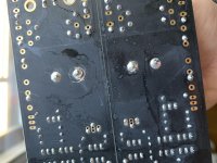
There is no danger to connect that particular pin wrongly with something. Its only ground plane it connects to underneath. On top side it connects on a copper patch for two bridge diodes common cathodes that through it go to ground again. If there is a fat copper cross linking the pad to the plane as an island makes no electrical difference to spill solder over it to scratched plane spots.
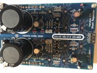
Thanks. Another set powered up on the first try. I am running these dual mono and M2s on each +/- boards are reaching about 48 Celcius after being on all day. I thought they would be shunting around 100ma, but it seems I could up the current a bit. Given their current temps, do you think increasing current could help at all?
I am planning to use the values suggested by George Swenson (I think) for the universal Rs and Cs values on the snubber.
I am planning to use the values suggested by George Swenson (I think) for the universal Rs and Cs values on the snubber.
Last edited:
Depends on sinks saturation level. If already well exploited, even little more current will be pushing temps upwards fast. Measure how much peak current is really going to the load. Subtract it from the CCS current. Shunt current is the answer. If M2 is shunting less than 100mA push the CCS setting to pass the 100mA spare mark a little. If already doing so, leave it alone. Staying around 100mA+ helps the Zo curve, say up to 110-120mA, but going over to 150mA+ it does not enough.
I have also read those "universal values" are likely effective, but I am not sure how near to finding exact ones for specific diodes bridge and transformer model de-ringing with a Quasimodo. In any case they can't break something, try them and listen for possible effect to the better or worse. Let us know.
I have also read those "universal values" are likely effective, but I am not sure how near to finding exact ones for specific diodes bridge and transformer model de-ringing with a Quasimodo. In any case they can't break something, try them and listen for possible effect to the better or worse. Let us know.
I have 3 pairs built now; when running dual mono and using one pair with MSRF860G diodes set to 325mA and the other using MUR120 and set to 200mA bass is noticeably stronger and more full bodied sound. When I swap to using two pairs using MUR120 and set to 200mA sound is flatter and harsher highs.
I would expect the difference to be the current, unless you think the MUR120 vs. MSRF860G would have any impact. I'll try pairs using the MUR120 and up the current to 275mA to start and see how they sound.
I would expect the difference to be the current, unless you think the MUR120 vs. MSRF860G would have any impact. I'll try pairs using the MUR120 and up the current to 275mA to start and see how they sound.
The MSRF is soft recovery too so its another class diode. Popular enough in powering digital. Could be both things you like. Bit more current needed, bit more suitable diode. You will decide by experimenting. That's the fun part. But de-ring first because accidental synergy differences with the transformer and the two different diode bridges could be key to your initial preference.
Kingbright LEDs
Hi Nick,
i ordered bib pcb to power my "pacific style" phono preamp. Now i am sourcing parts. The red kingbright LEDs as per BOM are not available at Mouser. Is it okay to substitute them with their orange counterparts kingbright WP2773ND?
Would they also be sufficient for a later use in a simplistic riaa build (old versions, non folded cascode)?
Thank you for your works, regards
Addi
Attachments

Last edited:
Yes, orange will do fine. The voltage range you want it for pays no attention to LEDs or PF5102s details.
Haven't used it that way. Post regulation is good as a concept, its the ground would remain contaminated with switching noise if it was originally there from SMPS. In other words its of benefit but not as much as if full linear.
Using it after SMPS the DC feed should be applied between the Rf resistor's input side pin and C1's zero Volt side pin. The bridge diodes can be deleted. Cx Cs Rs if used can be deleted too. Some 5V higher feed than the UBiB's DC output setting will do well. Little lower DC feed than that or higher enough can be tolerated.
Those things equally apply if someone has a DC line feed of high enough voltage and amperage already available from a linear PSU that he would like to post regulate. Avoiding yet another one transformer and a diodes bridge.
CX,Cs and Rs
Hi Salas,
What is your current opinion, sonically speaking, about including/not including these for powering my DCG3 build using the diodes as presently supplied in the kit.
Thanks. nash
Hi Salas,
What is your current opinion, sonically speaking, about including/not including these for powering my DCG3 build using the diodes as presently supplied in the kit.
Thanks. nash
Nash, really I haven't done the specific comparison. You will have to compare and decide yourself unless someone else here has done it already and he is able to enlighten us.
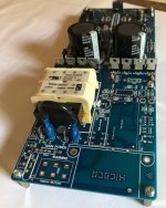
UltratBib SUB 1.3 adapted for my DIY project
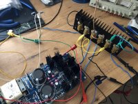
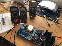
I would like to introduce my new PSU Board based on the original UltratBib SUB 1.3 design and the adapted ApexAudio ON/Off design.
I tested the ON/OFF design separately all ready and i just finished the test off the UltratBib with 2x12Vac Hammond transfo, with first R1 3,3ohm for 180mA and after with 2ohm for 300 CCmA.
I did first the test with 120ohm (100mA) and after with 49 Ohm dummy load (245mA).
I set the DCV for 12Vcc, after 45mns i had to adjust because it drifted a little.
Ripple 1.04mvpp for negative and 0,8mvpp for positive.
No oscillations, M1 and M2 for Positive and negative 32ºC, anyway very stable.
Now I will populate the ON/OFF part of the board, waiting on the components delivery...
Thank Salas and Mile Slavkovic.
Attachments
-
 IMG_2907a.jpg830.3 KB · Views: 268
 -
 IMG_2898a.jpg1,008.5 KB · Views: 262
 -
 IMG_2897a.jpg993.5 KB · Views: 259
 -
 IMG_2890a.jpg868.7 KB · Views: 268
 -
 IMG_2887a.jpg443.2 KB · Views: 427
 -
 IMG_2881a.jpg555.4 KB · Views: 435
 -
 IMG_2882a.jpg554.2 KB · Views: 441
 -
 IMG_2879a.jpg985.9 KB · Views: 462
 -
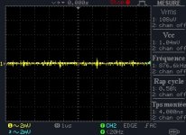 -12v100mA3,3ohm.jpg31.8 KB · Views: 259
 -
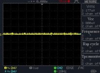 +12v100mA3,3ohm.jpg30.2 KB · Views: 236
Hi
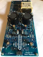
Nice combination board work. What is the purpose of the shunt reg section? Is it to power some active circuit in a signal path?
If you don't disturb the probe but you shut down the PSU power during measurement is the trace still looking about the same for its little noise? To can evaluate the influence of the bench setup. How much is picked up always and how much is inherent.
- Home
- Amplifiers
- Power Supplies
- Salas SSLV1.3 UltraBiB shunt regulator