DCG3 TEST
I want to share the results that i have using RMAA
Power Supply = +/-17.6v
Two L adapters and two transformers was used for power Supply.
Idle current = 100mA
Offset controller ,nothing special just a NE5532.
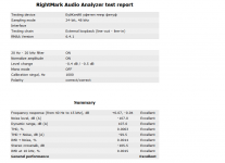
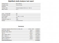
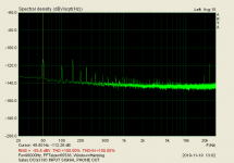
Tested at 1.6v RMS Line out.
Sound Card is an EsiJulia PCI.
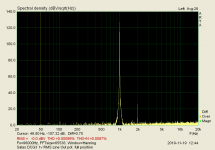
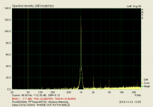
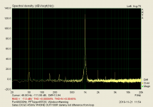
First picture is the Sound Card loop test.
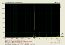
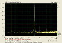
Second picture is the DCG3 test.
I want to share the results that i have using RMAA
Power Supply = +/-17.6v
Two L adapters and two transformers was used for power Supply.
Idle current = 100mA
Offset controller ,nothing special just a NE5532.
Tested at 1.6v RMS Line out.
Sound Card is an EsiJulia PCI.
First picture is the Sound Card loop test.
Second picture is the DCG3 test.
Attachments
Last edited:
Your audio card has far better channel separation and dynamic range than Alex's and mine. Happy to see that the DCG3 follows.
Stunning results. Congratulations!!! I also surprised that your PCI card has such low internal noise level. Excellent choice.
My new Focusrite v3 is not arrived yet, but I hope It will give me some improvement over v2.
I started to mod my 2nd DCG3 with LDR volume control and it is total disaster during first test due to that specific volume control. I’ll show you fist time taken FFT soon. So, LDR went to garbage can right away. Beside the fact of questionable implementation, it is also wrong type to use with DCG3. It is shunt type and has no constant input impedance. I ordered Khosmo (special order, ladder type, 20k, relay-based with remote and screen). I’ll test full combo soon and report accordingly.
Is it preferable for DCG3 to use constant input resistance over constant output resistance ?
My relay attenuator has the later and I'm gonna change the resistor because of the high output resistance (9K).
It's a relay attenuator and I'm gonna use it's calculator. So it's either
- constant input 10K resistance and variable output up to 5K or
- constant 3K output resistance ( for 300K load - DCG3) and variable up to 40K input resistance
Alexkosha what problem did you encounter with LDR ? IIRC you've tried the arduino based one from here which it's very configurable (e.g. load impedance)
Last edited:
Better go for constant output resistance. You can fix a bandwidth and rise time that way. Steady for all volume positions. Zo+R1 make RC time constant with C1. The R1 C1 are there to ensure stability when pot is at max. In other words when reduced to simply a contact with no Zo. Or when there isn't any pot but a straight input.
I find 20k ordinary log pot's 5k Zo nice (see post#20). Makes 1MHz worst case or about there depending on wiring. But its not written in stone. In any case I wouldn't recommend high enough pot Zo capable of shortening the bandwidth below 200kHz.
LDR attenuators usually add very significant THD of their own. Its due to non linearity in the light elements.
The programmable one from here is one of the best to handle.
I forgot to mention that a 10K log. potentiometer is in front of DCG3 during testing.
I have a new ARTA test using a non standard method and i will post this soon.
I have a new ARTA test using a non standard method and i will post this soon.
I will try to explain a bit although English isn't my first language.
It is a known problem when ARTA is used as fft analyzer and distortion meter.
GND loops is the first issue.
Voltage spikes due to noisy pc power supplies and digital signals transfer is the second, especially when a PCI sound card is used.
Another problem is cables and sockets that is used.
Trying to find a way for simply better looking fft i tryed this solution.
Trying to measure a circuit we really measure everything,gnd loops,voltage spikes,cables noise sockets bad contact,main hum e.t.c,e.t.c
Yes but we strongly interesting for the circuit .
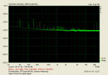
Lets see at the first picture.
In ARTA we choose GEN=EXTERNAL. PLAY.STOP.OVERLAY,SET AS OVERLAY.
Here is the line out under test when no input signal is present.
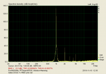
Lets see at the second picture.
In ARTA we choose GEN=SINE,OVERLAY,SHOW DIFFERENCE FROM OVERLAY,
That's it.
Please feel free saying your opinion.🙂
It is a known problem when ARTA is used as fft analyzer and distortion meter.
GND loops is the first issue.
Voltage spikes due to noisy pc power supplies and digital signals transfer is the second, especially when a PCI sound card is used.
Another problem is cables and sockets that is used.
Trying to find a way for simply better looking fft i tryed this solution.
Trying to measure a circuit we really measure everything,gnd loops,voltage spikes,cables noise sockets bad contact,main hum e.t.c,e.t.c
Yes but we strongly interesting for the circuit .
Lets see at the first picture.
In ARTA we choose GEN=EXTERNAL. PLAY.STOP.OVERLAY,SET AS OVERLAY.
Here is the line out under test when no input signal is present.
Lets see at the second picture.
In ARTA we choose GEN=SINE,OVERLAY,SHOW DIFFERENCE FROM OVERLAY,
That's it.
Please feel free saying your opinion.🙂
Attachments
Last edited:
DCG3 TEST
Different potentiometer positions.
Different potentiometer positions.
Attachments
Last edited:
DCG3 TEST
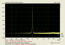
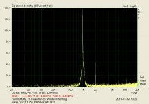
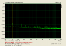
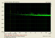
Phone Out.
R load=100R dummy load.
Picture 1,no input signal, pot in the position for 1v OUT.
Picture 2,no input signal, pot in the middle position.
Phone Out.
R load=100R dummy load.
Picture 1,no input signal, pot in the position for 1v OUT.
Picture 2,no input signal, pot in the middle position.
Attachments

Last edited:
Is it possible to keep the audio card's own loop without test tone as overlay and then show difference from a DUT's loop with test tone?
...So to keep canceling the PCI card's dirty grass elements as a standard while making various DUT measurements. For a certain gain level at least.
I think that i have the sound card loop no signal , With the same cables.Is it possible to keep the audio card's own loop without test tone as overlay and then show difference from a DUT's loop with test tone?
If not i will do this again.
Yes i will try your test tomorrow.
In any case, the picture without signal is more or less the same in every circuit that i tested.
Last edited:

Your overlay method works well to remove stored residual grunge I see.
It could be better demonstrated if you also have the first picture's clean up result to put side by side. Apples for apples.
Test tone distortion harmonics from a DUT may coincide with stored noise spikes higher up in the range though and THD profile proportions are going to be altered?
It could be better demonstrated if you also have the first picture's clean up result to put side by side. Apples for apples.
Test tone distortion harmonics from a DUT may coincide with stored noise spikes higher up in the range though and THD profile proportions are going to be altered?
I'm not sure exactly what that means.
Are you looking for a dirty test, in contrast to a clean?😕
Are you looking for a dirty test, in contrast to a clean?😕
Last edited:
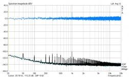
I'll explain with a picture. Shows the procedure and the cancellation for same loop's noise floor. So to be absolutely comparable. This is not looping a DCG3 by the way. Some hi-fi amp I had around.
Yes it cleans the spikes. A drawback I see is it also removes any 1/F rise information when there.
Another draw back I imagine is when there is a spray of spikes beyond the test tone (usually 1kHz) they will difference out real THD harmonics if we introduce a device under test and try to remove the audio interface's residual noise overlay.
Attachments
Is the black fft a sound card loop test(line out to line in) with Gen set to external?
Last edited:
It's an integrated amp added in the loop so to demonstrate the process better. Because my EMU external audio interface doesn't display enough harmonic noise of its own to help highlight a differential cancellation.
The loop with DUT saved as green overlay on gen external. The black is same with sine. The cyan is the difference. Same number of averaging in all takes. Volume zero.
The loop with DUT saved as green overlay on gen external. The black is same with sine. The cyan is the difference. Same number of averaging in all takes. Volume zero.
- Home
- Source & Line
- Analog Line Level
- Salas DCG3 preamp (line & headphone)