Hi, thanks for your advice on the line outputs. I hadn’t considered driving two separate circuits with the DCG3, but it is an intriguing thought. Perhaps I’ll try something like that later on.
Forgive the noob question, but so that I understand, the hp output would have 49.9 ohm in series (at Rzj) to have a similar signal level at the output? I believe at the moment I just have a jumper there.
Forgive the noob question, but so that I understand, the hp output would have 49.9 ohm in series (at Rzj) to have a similar signal level at the output? I believe at the moment I just have a jumper there.
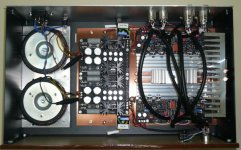
Very neat and professionally done!
Thanks Dewdrop. There were several iterations of the layout, and if I did it again I think I would mount the DCG3 and i-select vertically to shorten the input signal wiring, much like Salas and his friend did on their balanced build, and I think other members have done this too. Smart.
There are a few things I’d like to clean up, but for now I believe I’ll just enjoy the music.
Cheers!
Hi, thanks for your advice on the line outputs. I hadn’t considered driving two separate circuits with the DCG3, but it is an intriguing thought. Perhaps I’ll try something like that later on.
Forgive the noob question, but so that I understand, the hp output would have 49.9 ohm in series (at Rzj) to have a similar signal level at the output? I believe at the moment I just have a jumper there.
The HP output to the phones will continue to have the "zero" Ohm but the tap to the second line output will be geting the in-line resistor.
We are slowly finishing the true XLR (doubled up) version of my friend's also.
Hi Salas,
Interesting! Is this transformer BAL/SE input?
SE to BAL config Sowter. For also having one single ended input properly converted in two opposing phases. All other inputs BAL only.
I
I was listening to the Te Kanawa/Popp/von Stade recording of Figaro, and my wife looked at me quizzically because my eyes were misting up. Ahh, she knew.
Ah, the feelings. Makes it all worth it.
Yes, it gets away fine, has 100mA bias with a thick alu plate that augments at the chassis. No worries for HP max power output in moderate bias because on the bridged (so called BAL) headphones connector it will produce 4x the mW of SE.
Not sure if I understand correctly. Do you mean that the heavier the load the less the heating on the heatsinks?
No, I mean we can use 100mA bias for less heat even for insensitive headphones when doubled up BAL. Because its bridged drive. Double the voltage from two phase amplifiers quadruples the power output.
Howdy everybody, I've begun this adventure and I have the wonders... I'm combining this preamp that will run my two phono sources that require gain with an Aikida tube buffer that will have a pad for components that are already outputting too high a signal for a power amp, sooo, I'll need a slightly complex relay system to not only route the inputs to the correct boards, but also share a common volume pot. The relays I chose are 12V varietal and there are four of them. Can I run them all off of the 12V relay circuit on the amp board? Thanks for any time taken to consider this question and respond as well.
The 12V on the DCG3 board's output relay is good for that one only. The three LEDs for dropping the +Rail can't take more.
If you also got the I-selector board, it already has a 12V chip regulator and auxiliary DC output connector pads from that.
If not, a way is to tap raw DC from a reservoir capacitor on the DCSTB PSU to feed a 12V chip regulator for your purposes.
If you also got the I-selector board, it already has a 12V chip regulator and auxiliary DC output connector pads from that.
If not, a way is to tap raw DC from a reservoir capacitor on the DCSTB PSU to feed a 12V chip regulator for your purposes.
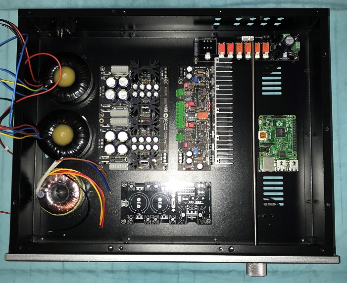
I see, thanks! Still, mine biased at 112mA gets hot and I had to build the heatsink like this.
Your build is very nice. Differently interfaced to the sink. I will let you know MOSFET tabs temperatures when we will finish our version of build. Due to the many big peripheral things my friend wanted to include we have no floor space left and we can not do much more than the thick Alu plate interface bolted to the chassis scenario.
I had space limitations too. Those heatpipes for computers work very well to transfer heat to the heatsink right under the top plate ventilation grilles.
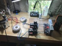
Finally getting around to putting mine in a box. Just for good measure I'm going to stick an L-Adapter and RPi in the box as well. How does this layout look? I've tried to keep the transformers as far as possible from the DCG3 and the RPi:
- Home
- Source & Line
- Analog Line Level
- Salas DCG3 preamp (line & headphone)