Check if R10 had held well too.
Salas,
R10 held and all the FETs are energizing quite well with zero offset, BUT, it's that 6v Delta at the PSU output that tells me something got damaged.
I have a FET testers, but I just don't know if it would tell me enough.
Cheers,
Greg
There are BC TO-92 driver transistors near each TO-220 main BJT in DCSTB. Those could be knocked out first. Vbe measurement will tell. Normal one should be 0.6V +/- some. Measure for the big BJT too while you are at it. JFETs you can compare with healthy ones if RDS falls in the same range or not (resistance from drain to source when not powered).
Nick,
DCSTB seems to have survived. However, I did measure RDS difference on the M1. I will start there.
Thank you!
Greg
DCSTB seems to have survived. However, I did measure RDS difference on the M1. I will start there.
Thank you!
Greg
For a MOSFET, when powered, more secure is to compare Vgs with the healthy one of same position in the good channel. As a matter of fact you can compare many steady state voltages to the healthy channel using it as troubleshooting reference map.
Hi Salas,
I have my DCG3 for a while now and super happy with it. The only thing I forgot to add is a switch between HP and speaker outputs since I'm using both. What would be the easiest to do it without impacting SQ?
Thanks in advance!
I have my DCG3 for a while now and super happy with it. The only thing I forgot to add is a switch between HP and speaker outputs since I'm using both. What would be the easiest to do it without impacting SQ?
Thanks in advance!
As it is has two outputs routed working in parallel. One preamp one headphone. You could add a front panel switch controlling a relay near the back panel RCAs to turn the preamp output on/off.
Better have that relay's input going signal hot/ground so it shields the output from interference when selected "off" i.e muting to ground.
The simplest way is to add nothing and just turn the power amp off when you don't want to listen through speakers of course. But its the least elegant way.
Better have that relay's input going signal hot/ground so it shields the output from interference when selected "off" i.e muting to ground.
The simplest way is to add nothing and just turn the power amp off when you don't want to listen through speakers of course. But its the least elegant way.
In It’s Home
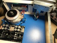
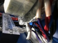
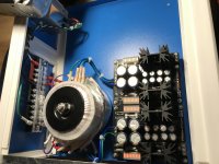
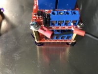
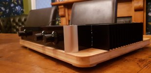
Howdy, friends, just finished putting the DTSTB and accessories in their new home. I have left room for a GlassWare PS-Tube and Hammond 270CAX In there as well. I’ve got the proper empties on the terminal block and can now start looking forward to the aviation connector. It’ll have 11 active pins, and this brings me to the question of the night...
Can I use a single ground between the two outputs from this PSU? I understand that ground is ground, but I didn’t know if there was any referencing happening there because honestly I don’t really understand that mess, yet.
One consideration... the foil lined cardboard between the two trannys is getting replaced by something laser cut and pro looking, so don’t judge me till later. Comments? What can I do better? Tonight to start the amplifier chassis, right after I play my banjo for a minute.
Attachments
Better don't use a common PSU ground umbilical wire if you can. It may create a ground loop i.e. some hum.
Thanks, exactly what I needed to know, now to gather some well shielded 12-18awg cable that’s just a little bit flexible.
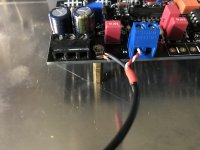
Hey there, I’m seeking advice, and your opinion on whether I need to be pulled back from the edge. I made the mistake of reading about grounding. By that I mean, holy jeeze, just scratching the surface gave me a compound headache. Here is what I took away from what I read, though. Please forgive if I missed the point, at least I’m trying. Balanced, we’ve been doing it wrong. At least as it pertains to shielding. This guy said not to tie the shield to 0V and signal ground by grounding only on one end. He said to ground the shield to chassis ground for effectiveness and avoidance of ground loops. There was a lot more and I’m trying to get at it , including all the different methods of finally marrying signal and chassis with resistors, capacitors or diode or combinations of these.
So, to this end, I’m attempting to follow this method from RCA to amp input. I’ll run an independent wire from the signal ground tab on the RCA plug to the ground, return? 0V? Input on the board. Overkill? Or will it potentially cutdown or eliminate cross talk from cable inductance? I’m on a quest for the deep and wide image, my speakers are very capable (and I’ve got some Polk SDA’s on deck) and even though I made some egregious mistakes in the headphone amp I’m using as a pre right now,? I still get a wonderful soundstage with very poor stereo isolation, so I’m hoping this will fix that. Call me anything you want, just be honest before I do this with all four inputs in this amp.
Picture.
Attachments
Last edited:
Right, I do understand that, what I’m taking away is the separation of signal ground and chassis ground, how to successfully connect them and where, and is this method of shielding inherently better. Not in a balanced system, but in any case. What is your opinion on grounding a shield and for signal, at the point in which I’m grounding to chassis, is it beneficial, benign, or bad?
In this preamp we were usually connecting the pcb's front lane (that carries all the signal returns) to the chassis at one point with a wire. That worked as there was no hum. You do it one by one directly to the chassis now but the pcb must also have a reference back from the chassis in the end. As to what is gonna be better in the specific situation I don't know, its a practical matter. If you will have hum you should change it.
I need advice from you guys, particularly from you who is using Khozmo attenuators. I played enough with my LDR based attenuator and want to go back to classic one. Two reasons that I want to change it: A: 21 steps of my LDR are way too rough and I have too quite or too laud at two-three steps that I feel comfortable with my volume level. B: it is shunt type (means constant resistor in parallel and changeable resistance to the GND. As you imagine, it is not a constant impedance at my input. I use 25K 47 steps Goldpoit (they do not have 20K) on my other (in office) unit and it is very nice one. However, I would like to have one with remote control for my home use. Unfortunately Goldpoit is not manufacturing these with remotes. I see Khozmo has such devices, but I never used any product from these guys. How are these units perform? What is your experience with that brand?
High Quality Audio & Industrial Attenuators
High Quality Audio & Industrial Attenuators
@ aheck
You might want to have a look at this post:
https://www.diyaudio.com/forums/ana...ectors.html?highlight=earthing+pre+amp+inputs
There's loads of differing opinions on earthing, I use something close to scheme B on this post with a common earth from L & R on each input going to an i-Select input board which is then connected to the DCG3 board. As Salas said, the front common ground rail on the DCG3 board is connected to chassis ground, in my case I used a loop breaker and kept all the RCA's insulated from the chassis. The body of the volume pot is also grounded to the i-Select earth. It works, no hum and excellent stereo imaging.🙂
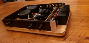
I've spent ages getting the front panel looking the part, hence the reason for the delay in getting all the wiring done. I won't post any pictures of the front panel til I've got it assembled and working 😱
Looks good. The other psu was for an Rpi yes? I know you are nearly there now but I recently powered my Rpi and dac separately using an Iancanada isolator. Made a big difference.
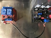
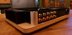
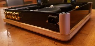
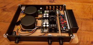
Slow progress for me too. I had a change of plan and decided to use an I select board as is located the pot better. Managed to use 3 pin headers to get the dact type ebay pot on there and I reused some Japanese relays I scavenged from an old dvd players Scart board.
Its tight in there so I hope I'm good for cable routing versus noise. Soon see.
Obviously I'm all wood and acrylic so I'm not sure what to to ground wise.
Attachments
- Home
- Source & Line
- Analog Line Level
- Salas DCG3 preamp (line & headphone)