A pot (wired as volume control) when at minimum shorts the signal to ground to mute it. Gradually develops resistance across hot and ground in a logarithmic fashion as we turn it up for the input signal to grow stronger across it. Consequently across the preamp's input too. The preamp's fixed input resistance lays in parallel to the pot's at any position.
It was the varying resistance between L and R that puzzled me but thinking about if there is only 2 ohm between L / G and R / G then from L to R is also going to be low.
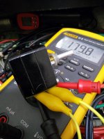
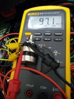
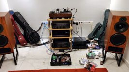
Much much better! But looks like the Allo Boss is taking the power and feeding down to Rpi
OT also....sorry....but what is the ribbon cable? Into the Pi
There's an Isolator fitted between the Pi and Boss. Power for the Boss is from the L-Adapter and power for the Isolator/Pi is fed from an external power supply - you can see the cable coming off the right hand side of the isolator and going to the rear panel. I'll be using an L-Adapter in another case to power this.
The ribbon cable is an SD card extender which goes to the back panel so that I can change the Pi's SD card without having to open up the case.
If you are using Ian's isolator, the L Adaptor can supply to the Pi through the GPIO pins too.
It was the varying resistance between L and R that puzzled me but thinking about if there is only 2 ohm between L / G and R / G then from L to R is also going to be low.
When the pot's return pins reference to GND their two sections then relate in series.
The channels grounds will eventually meet somewhere in a system. In this case at the selector board.
Let me demonstrate with two iconic Japanese carbon pots. Alps Black Beauty 2x100k nominal log & Tocos Cosmos 2x50k nominal log.
The yellow lead connects their number 1 pins together. They appear at 2x their measured section value when set at max and measuring between their wiper pins. They also show near zero when set to minimum and everything in between when turning the shaft.
Attachments
If you are using Ian's isolator, the L Adaptor can supply to the Pi through the GPIO pins too.
Its an Allo Isolator V1.2
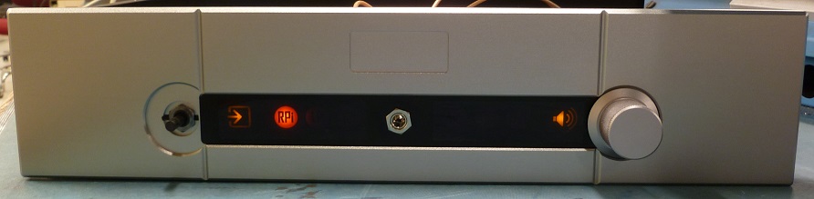
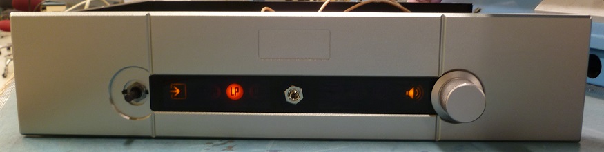
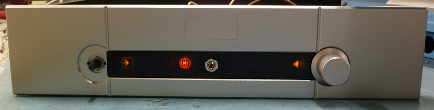
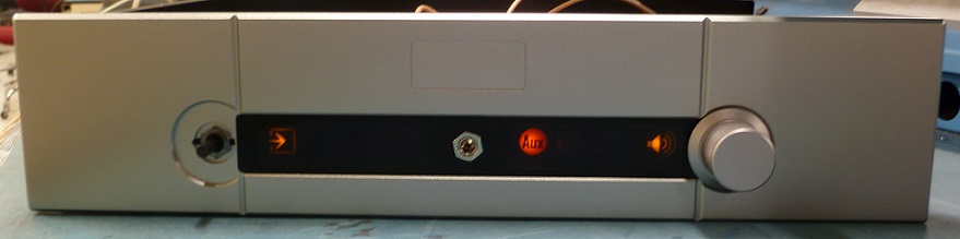


Brilliant! Like the visual source icons.
I have a Kali so it will make your music better. ;-)
I have a Kali so it will make your music better. ;-)
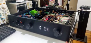
My friend Tony finally finished with his DCG3 doubled up XLR build after the summer break. He came over so I checked with bench equipment and headphones that his wiring was working correctly, he took it away to connect into his system.
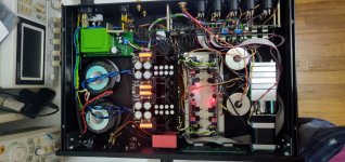
Me I assembled his PCB kits and guided him for the rest of works. For the mirrors I matched and put BC327-40s of my own because these are older kits with no such type option. At an earlier time debugged the automation wiring and modified its third party wrongly done PSU also (green board at back left, has stuff underside too).
I never assembled from Tea's complete kits before as I only did prototypes. No wrong values and intuitively organized. The two boards came up just 0.9% apart in total mA consumption. Nice to see output bias current was hit on the head between random sets as an end assembler when M3 VGS(OFF) was selected for a number of kits by someone else. DC offset could be readily adjusted to zero and stay there well steady before applying the watchdog op-amp servos for long term safety.
Here I must congratulate Tea-Bag for parts matching and general quality. The kits gave me no hard time at any point.
Tony sounded enthusiastic over the phone on first try. I visited Tony's audio den after few days and the subjective result was fine indeed.
He has a VPI Classic turntable augmented with Falcon & Roadrunner motor control, a ZYX carbon cantilever recent type cartridge (Ultimate Airy?), VPI's own ten inch uni-pivot arm.
Bryston BCD-3 CDP, Nak DR-2 cassette deck, FSP phono, Bryston cubed series 4B3 2X500W/4Ω Power amp, PMC IB2i 4Ω studio monitor grade TL loudspeakers. There was also a Bryston BP26 pre with phono module and external PSU on his rack that he was evaluating.
His other preamp is a Benchmark DAC3 HGC which is not only DAC but has line level and phones amp remote controlled facilities too (not shown in the photo).
This true balanced DCG3 preamp build uses expensive solutions from Khozmo and Sowter. Quad motorized 48 steps 25k series resistors pot, six way XLR double deck relay source selector, big rotary encoder, micro-controlled automation with remote & dimmable dotted display, SE to BAL 1:1+1 Tx for input #6, custom chassis work. Power trafos are from Toroidy and there are both 4pin balanced XLR and SE jack Neutrik headphone connectors with safety locks.
As Tony opted for this config to connect and control his own sound system needs easier, he is naturally happy with the functionality result and look.
The consumption measured 30W from mains, 36W when the pot motor runs, 2.5W on standby. The box's bottom goes hot but comfortably hot, the top cover is colder, rather lukewarm. The various heavy parts add thermal mass to the chassis floor soaking somewhat more than usual dissipation.
Attachments
Hi Salas,
By doubled up and true balanced do you mean two DCG3 boards with each board being a + and - phase for a channel?
Is the Khozmo you mentioned a 4 deck shunt version with 25k series resistor for each leg? Any idea what brand of series resistor is being used?
Thanks. nash
By doubled up and true balanced do you mean two DCG3 boards with each board being a + and - phase for a channel?
Is the Khozmo you mentioned a 4 deck shunt version with 25k series resistor for each leg? Any idea what brand of series resistor is being used?
Thanks. nash
Yes, each board's two sections are used for amplifying the positive and negative phases of one channel's balanced signal. Only input #6 is RCA but the Sowter transformer creates a true balanced signal out of it. Brings it up to XLR status.
If I am not being wrong it should be the type 1475 but in an alternative metal can mount version: 1475 High Impedance Input Phase Splitter Triad HS-29
The Khozmo is the series resistors quad attenuator version, not shunt. Equivalent to a typical series pot. I don't remember if Tony mentioned the resistors brand to me. He is away, I will send him a message, maybe he can post more info.
OK so it is similar to my build. DCG3 sounds great driving my newly built Sony Vfet amps. Using the Vfet amps for the mid/tweeter for my OBL15 and the F5TV3 for the bass. Large scale orchestral works sound stunning.
Thanks. nash
Thanks. nash
Very similar. There have been not many balanced builds in the thread. One of them is yours. Throughout balanced, not just balanced impedance differential input, its costly and busy to make.
Its alike bridging stereo power amps reducing them to half the channels. As they do in professional installations when they need tons of more power but simply have extra numbers of the same model available. That is why the max power figure in the four pin "balanced" headphones output quadruples in this kind of DCG3 builds.
Its alike bridging stereo power amps reducing them to half the channels. As they do in professional installations when they need tons of more power but simply have extra numbers of the same model available. That is why the max power figure in the four pin "balanced" headphones output quadruples in this kind of DCG3 builds.
P.S.
While the common mode interference is well fought when present and the signal voltage doubles in a balanced interface, the circuitry's inherent noise floor goes up by 3dB and its output impedance doubles.
Double the sections to handle symmetrical phases, double the pros & cons. Cons not felt in line level. But 3dB could be a consideration in phono preamp design and higher Zo a consideration in power amps application.
Have you seen professional amps rated at double the loudspeakers Ohm for bridged configuration than rated in stereo mode? Effective Zo doubles because now the channels are flanking a floating load with their individual Zo. Damping factor halves.
Their PSU is designed for two channels current not four. Rating the permitted load at double the Ohm bridged, allows the power to quadruple due to output voltage doubling but without challenging the current reserve and the damping.
Puh... At the moment building a balanced one with four toroids abd 4 psu, muses volume controller, six balanced inputs... I think I will use one case for the psu ans one for the rest [emoji23]
Definitely. From the moment on you introduce as many PSUs as preamp sections, one box is simply not enough.
Hi!I am Nick's friend,Tony.I am away for some days,so i am posting this from my phone,i will be quite quick.the dcg3 in balanced version we built is extremely transparent,and has great dynamics.i was listening the last month a bryston bp26 pre and a cubed bp17.the dcg3 is in another level.so, about the resistors in the khozmo pot,i really don't know their brand,but i think it is very good solution if someone wants a really good pot.i want to thank Salas for his help with the whole project! dcg3 is an amazing preamplifier,with tons of power and control over the amp.
Can somebody provide a part number for fuse clips that fit? I'm having a hard time finding these.
Thanks,
David
Thanks,
David
- Home
- Source & Line
- Analog Line Level
- Salas DCG3 preamp (line & headphone)