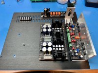
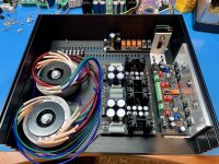

A few steps closer, mostly wiring and back panel left to do.
I like your attenuator mounting bracket. Did you make it yourself or have it fabricated? It looks like it is well-made.
I like your attenuator mounting bracket. Did you make it yourself or have it fabricated? It looks like it is well-made.
Yes, it seems to be well made. Part of a kit with rod and bushings from Parts Connexion in Canada.
BK
I have a complete set of PCB's which I will not use.
The design I want to make leaves too little space in the enclosure for this.
It is only the bare PCB's ( no components ) for the dual P/S and pre-amp.
PM me if interested.
I live in the Netherlands - Europe.
The design I want to make leaves too little space in the enclosure for this.
It is only the bare PCB's ( no components ) for the dual P/S and pre-amp.
PM me if interested.
I live in the Netherlands - Europe.
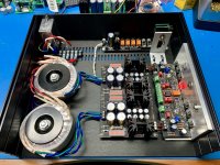
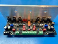
I like the detail where the rail lines links are from thick magnet wire that the insulation varnish is stripped off just so as to fit the sockets but to mostly remain at the middle.
Even the signal input shorting links for the initial testing are carefully bent to a Π shape. The shrink wrap on the mirror transistors is white to match the color of the thermal paste line between them. There are also wire pins to can hang steady hook probes off the output connectors.
Attention to details, immaculate construction, sure footed testing.
Thanks, Salas, for noticing. I build carefully and at my own pace and only when I'm in right mood. Details matter, at least for peace of mind and satisfaction. Good catch on the magnet wire - it was handy and seemed like a match. I also tinned the ends where I scraped off the varnish to avoid future corrosion 🙂
BK
BK
Salas,
I just pulled my DCG3 board off the shelf after a year, hooked it up to the DCSTB, bias is at 7R5, R10 approx 1.1vdc. Offset all out, but I have a whopping 6 volt differential out of the DCSTB when powering the right side of the board (side that Ca is situated on). REF led bar full brightness on one side. Once I disconnect that channel from the DCSTB, voltage outputs return to balanced, with the REF leds balanced. Tried both sides on each side preamp board, and it’s just that side of the preamp.
Everything was working last time I used the board, and the DCSTB has worked flawlessly with other projects. So, definitely the DCG3.
Any ideas?
Cheers,
Greg
Either an insulation problem on the MOSFETs mounting or something wrong with the relay circuit I would first think. Are all tabs checking with no shorts to sink or chassis, does the relay click?
Do the DCSTB sinks on the fully bright going side become hotter than those on the other side? Are the DCSTB power transistors tabs showing discontinuity to chassis as they should?
Do the DCSTB sinks on the fully bright going side become hotter than those on the other side? Are the DCSTB power transistors tabs showing discontinuity to chassis as they should?
I also tinned the ends where I scraped off the varnish to avoid future corrosion 🙂
😉
Nick,
I reversed polarity that channel. I replaced the electrolytics, but I must have damaged the fets.
Just replace all the semis in that channel?
Thanks,
Greg
I reversed polarity that channel. I replaced the electrolytics, but I must have damaged the fets.
Just replace all the semis in that channel?
Thanks,
Greg
Oops. The MOSFETS tried to run about 1.5A through them although the supply should have limited it by the voltage drop you saw and it should have helped. The input side JFETs and the BJTs should have stayed at nil current. If DCG3 shows it did not survive indeed, I would start with M3 (DN2540) which would be the most vulnerable to the rails reversal incident.
Did the electrolytics manage to bulge? Was it working in reverse for a long enough duration? Any smoke or discoloration signs on any components?
Did the electrolytics manage to bulge? Was it working in reverse for a long enough duration? Any smoke or discoloration signs on any components?
- Home
- Source & Line
- Analog Line Level
- Salas DCG3 preamp (line & headphone)