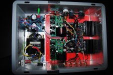
Colorful and nicely reordered. PCBs for everything now I see.
1.2Rs of narrower loops etched layout replaced the perfboard ones? What type of comp cap (C2) you ended up with? SMica?
BTW no Selectronic anymore I read somewhere in the forum. Closing down. Shame for we lose their R-Cores option.
after changing the shunts with new ones prepared for 17v and also changing the compensation cap in the dcg3 feedback, it sounds spectacularly well with my new mosfet power amps.
1.2Rs of narrower loops etched layout replaced the perfboard ones? What type of comp cap (C2) you ended up with? SMica?
BTW no Selectronic anymore I read somewhere in the forum. Closing down. Shame for we lose their R-Cores option.
I am already trying to source rcores directly from India.... Will let you know.
The DCG3 always sounded slightly etched and I believed the fault came from the amps or other components but while studying compensation schemes for my power amps and after much experimentation I understood that a slight change in value could tame the highs so I increased the FB bypass cap until I got the good sweet treble I was searching for.
Now it is really outstanding.
Last edited:
I heard that about Selectronic. Lucky I got two r-cores from them for my DCG-3.
But I also have another r-core I got from china for anothr DCG-3 that I have with BIB power supply. Haven' t install it yet, but usually r-cores are good quality.
But I also have another r-core I got from china for anothr DCG-3 that I have with BIB power supply. Haven' t install it yet, but usually r-cores are good quality.
I am already trying to source rcores directly from India.... Will let you know.
The DCG3 always sounded slightly etched and I believed the fault came from the amps or other components but while studying compensation schemes for my power amps and after much experimentation I understood that a slight change in value could tame the highs so I increased the FB bypass cap until I got the good sweet treble I was searching for.
Now it is really outstanding.
On my speakers system and on my various headphones 33pF is rendering a characteristically non etched treble but 39pF is stable also. I had SMica handy.
Maybe it has to do with fine tuning to different power amps synergy. Which op-amp model you use in the servo and what value/type is your optimum C2?
Have Selectronic actually finished trading or could I order an R core before they do?
Their website is up and offers 40% discounts. Although some said they don't answer emails.
Thanks Salas I checked last night but could not place an order. I might try phoning but don't speak French so it could prove interesting😀
OPA2604APOn my speakers system and on my various headphones 33pF is rendering a characteristically non etched treble but 39pF is stable also. I had SMica handy.
Maybe it has to do with fine tuning to different power amps synergy. Which op-amp model you use in the servo and what value/type is your optimum C2?
SM 163p
Throwing away much phase margin with 163pF C2 though. Try AD823 DIP8 (European stockist) AD823ANZ ANALOG DEVICES - Operational amplifier | TME - Electronic components
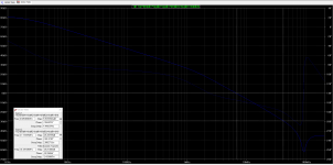
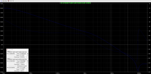
Its different set of graphs than my simulations. Both for numbers and shapes. I get 66.5 deg of margin with 33pF and 27.4 deg with 163pF. Also more open loop max gain. It was not the Tian method you use and if we also have different models our deviations can add up.
But... Before theory, in practice, I compensated the circuit sans input pot on the bench and then listened to it also. I remember that significantly higher value additions took it nearer to instability indeed.
Nonetheless practical matters like pots, wiring, type of PSUs, range of loads I want unconditional stability (included many tested headphones), can play a significant role for compensation choice.
I just don't recommend hit or miss value substitutions to people that don't have lab equipment. If it works stably for you that you can fully test it for some purpose, then its fine.
You are correct, I am not having good results with this TIAN probe.
In my setup it works perfectly.... But I also do not recommend my mods in other situations.
In my setup it works perfectly.... But I also do not recommend my mods in other situations.
I did not test it with a low ohm headphone.... do you believe I might be in danger if I load the output with a 33ohm for example ?
your phase margins are exceptionally low.
For basic operation one expects a phase margin of ~45degrees, but that will give lots of overshoot on fast signals.
One normally needs at least 60degrees of phase margin to get minimal overshoot and usually amplifiers perform better with around 80degrees of phase margin.
I do not know is your simulation is correct, but you can check by testing your amplifier.
Put in a lowish level of 1kHz square wave with the input filter crippled.
Check the output for a clean square.
Add some capacitor load and repeat. Try 1nF, 3n3F, 10nF, 33nF, 100nF
Do any increase the overshoot?
Do any start ringing?
Do any cause oscillation?
Crippling the input filter:
Do not remove it. If it is set to 200kHz, then move it to 2MHz
i.e. change it by one decade.
- Home
- Source & Line
- Analog Line Level
- Salas DCG3 preamp (line & headphone)