Nice 32Ω load sim but Fet Spice models can be difficult. For real world comparison and possibly bit of sim tweaking there are couple of Grado SR60 32Ω used as load THD vs Frequency plots in post#1 among others. One at 100mA output stage bias and one at 150mA. 0.0051% & 0.0022%. Both 2ndH dominant. Both taken at 0.4V RMS output.
Try LSK389 spice model also which is closer to μPA68 gfs. Weird to remove a Mosfet from an eight semiconductors circuit and see no change in a sim. At least a small clue of topological change. There was a measurable benefit to add the cascoding Mosfet while on the bench when I was developing it. Even progressivly higher rails were making a difference. More VDS is less Ciss, Crss etc. Possibly the sim does not see as much first stage difficulty as of driving the real output stage with its layout parasitics.
Some short video of a loudspeaker playing music just on DCG3 with your pictured RCA to SPKR cable adapter would be a true spectacle. On the other hand wouldn't you prefer the headphone output jack that doesn't have a line out buffer resistor? Or you bypassed the R15 to RCA?DCG3 biased at 150 mA is even enough to drive efficient loudspeakers to the enjoyable quiet listening levels. I encourage everyone to try. You may be amazed with sound. Mine are 90 dB/W and mostly 4 Ω. With loudspeakers close to 100 dB/W, it will be loud. Simple adapter:
Yes, R15 is replaced with jumper wire in my build. I wanted low output impedance for direct driving VAS transformers, common in various Pass Labs section amplifiers. It proved to bring much better sound than usual JFET input buffer, at least by my perception. Objective measurements confirmed less distortion, better harmonics distribution and extended frequency response.
https://www.diyaudio.com/community/threads/ludef.369990/post-6845895
As for driving loudspeakers with the DCG3, it was an idea to use sound of audio chain with very minimum of really good components, as comparison reference in evaluating changes introduced by amplifiers and power buffers after the same DAC/preamplifier.
Anyway, sound of the DCG3 alone driving loudspeakers, proved to be excellent. Nothing less to expect from a single ended class A with such low distortion and high bandwidth.

what is/would be the advantage of using Mark's famous H9kpXG
(I saw that Pfarrell and others are using it, while I always looked at it as a sort of softstart for power-hungry output-stages)
?
(I saw that Pfarrell and others are using it, while I always looked at it as a sort of softstart for power-hungry output-stages)
?
With H9KPXG, some convenient options are available, like ability to use any type switch (momentary or latching) and you don’t have to route high voltage to the front panel. Mains voltages can remain in the isolated compartment, improving safety. That’s all I see as a possible advantage in case of using it with preamplifier.
Stuffing Q:
C5 is 0.15 uF 63V Lima MKS2
Cb Cc is 0.15 uF 63V Lima MKS2, too.
In the kit, I got 2 smallish 0.15 63 and 2 biggish 0.15 100
Images from other builds say the (small) 0.15 63 go into Cb/Cc, the 0.15 100 into C5
correct?
Aside the voltage, is there a "quality-difference" between the two?
Many thanks
C5 is 0.15 uF 63V Lima MKS2
Cb Cc is 0.15 uF 63V Lima MKS2, too.
In the kit, I got 2 smallish 0.15 63 and 2 biggish 0.15 100
Images from other builds say the (small) 0.15 63 go into Cb/Cc, the 0.15 100 into C5
correct?
Aside the voltage, is there a "quality-difference" between the two?
Many thanks
The bigger ones are MKP. They are for the across op-amp integrator positions (C5). They are not there in the generic parts prototype photo of post#1 but they are there in the build guide's main photo. After the BOM was final. C5 width outlines on PCB are double indicating two possible sizes. Can also be MKS but I thought MKP was a wee bit better for HF in C5 position. I could not subjectively find enough of a difference between MKS and MKP for the other positions in this circuit. Which are for input filter and local rail decoupling in the op-amp or local filtering in the cascode's voltage bias divider.
Wohoo, I’ve done it right
Thank you Salas!
Ps: is there a reason Cb / Cc are not populated (in the build-guide‘s foto)?
Thank you Salas!
Ps: is there a reason Cb / Cc are not populated (in the build-guide‘s foto)?
They are populated. But under the board. You may see soldered pins if you look closer on their pads. To can pry off the IC from the socket easier without nearby obstacles. Additionally there are SMD pads for C0G low profile Cb Cc. No SMD pads on the test board pics but existing on all GB released PCBs.
I must say, I have no words for this level of perfection!
I should adapt and learn to look much more thoroughly, everything is there, but how to see it when unaware of what to see ☺️
I should adapt and learn to look much more thoroughly, everything is there, but how to see it when unaware of what to see ☺️
Heatsink-Question:
The build-guide recommends a heatsink 1.2C/W or 1C/W or a bar mounted on the bottom-plate.
I wonder a bit, as the heatsinks with those values are pretty whoppy beasts!
The build-guide recommends a heatsink 1.2C/W or 1C/W or a bar mounted on the bottom-plate.
I wonder a bit, as the heatsinks with those values are pretty whoppy beasts!
If the sink sits inside the enclosure with closed lid and the bias is 150mA on two channels it carries you would be surprised on how easily the sink heats up if moderate sized and without good air circulation in its vicinity. It takes both top and bottom vents by the way. I recommend using the enclosure for sinking via a Mosfets mounting bar. Or a side panel exterior sink type. A hefty enclosure like you guys usually employ has good metal mass and area spread while it thermally communicates with the room's air.
Ah yes, now I see, of course.
(Just like the rather big heatsink in the DCB1 mez 🙂 )
This DCG3 will run at 100mA as my HP (kef M500) seems to be a sensitive one with 32Ohm, and I „never“ listen on high levels… (now if only the covers wouldn‘t fall apart, they look gorgeous and sound quite nice but of a lousy build-quality!)
Thank you, Salas!
To give you an idea see post#5 picture #2. That was a beta testing friend's 100mA veroboard build he attached to an internal sink. It was a sizeable sink. But with restricted circulation even of immediate in-box air, as he installed the sink against a side panel, I remember it to get substantially hot.Ah yes, now I see, of course.
(Just like the rather big heatsink in the DCB1 mez 🙂 )
Thank you Salas!
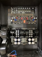
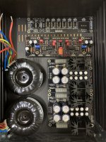
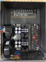
I go with the jets on a bottom-plate (with good, additional passive aeration)
Is one layout technically better than the other?
For its symmetry, I prefer the symmetric layout, but the third option should be working too… (temp issues maybe?)
I go with the jets on a bottom-plate (with good, additional passive aeration)
Is one layout technically better than the other?
For its symmetry, I prefer the symmetric layout, but the third option should be working too… (temp issues maybe?)
Attachments
- Home
- Source & Line
- Analog Line Level
- Salas DCG3 preamp (line & headphone)