....Henry’s build is fantastic.... so to go along similar lines I’m also going to try solid rails like Henry did above but will look at Servo-City as they have similar x-rails like MakerBeam but are in the US so shipping should be cheaper
X-Rail is another good choice, but a little larger in cross section. If you are interested in MakerBeam, Amazon has them in stock in the US.
Edit: Ah, you are in Canada. Cripes, much more expensive on the amazon.ca site, sorry.
-Henry
Edit: Ah, you are in Canada. Cripes, much more expensive on the amazon.ca site, sorry.
-Henry
Last edited:
Openbuilds sells 40 x 40 linear rail with the appropriate connector hardware at a fairly reasonable price that should be perfect for this application.
[URL="https://openbuildspartstore.com/linear-rail/?gclid=Cj0KCQjw0oCDBhCPARIsAII3C_GOXLY7W8CdqwZl67vyXq9H4g1ggbrbOjSP1shdTI32V3CSBwp2JV0aApp5EALw_wcB"[/URL]
[URL="https://openbuildspartstore.com/linear-rail/?gclid=Cj0KCQjw0oCDBhCPARIsAII3C_GOXLY7W8CdqwZl67vyXq9H4g1ggbrbOjSP1shdTI32V3CSBwp2JV0aApp5EALw_wcB"[/URL]
Henry,
How did you go about getting all of your little drill marks for the volume controls so perfect? Did you create a template?
Alan
How did you go about getting all of your little drill marks for the volume controls so perfect? Did you create a template?
Alan
Yes. If you look at the third picture in post 5553, I made a template from PC board material. I created a footprint in KiCad starting off with a pair of vias that I repeatedly duplicated and rotated in 15 degree increments. I printed out the footprint, glued it to the board, then carefully punched the centers with a carbide scribe. Using a magnifier, I drilled the template with a 1/16" bit. I marked the panel with perpendicular lines and taped down the template with the holes centered over the lines. Then I drilled the panel with a shallow stop set on my drill press. After painting the panel gray, I used a toothpick to apply white acrylic paint to the holes. It takes many coats because the paint shrinks as it dries. Fortunately you don't have to be too precise with the infill paint because you can wipe the excess away with a wet paper towel before it dries.
This is a lot of work, but yields benefits for both aesthetics and functionality.
This is a lot of work, but yields benefits for both aesthetics and functionality.
@hpasternack - impressive job on that front panel.
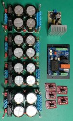
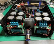
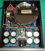
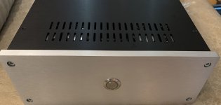
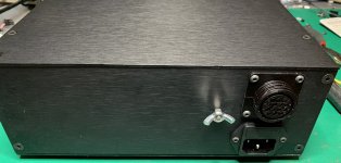
I finally got around to finishing the power supply for my preamp. This is in a separate box with a 14 conductor DC umbilical to the main chassis. The power supply has four separate +/- supplies (two of which are about +/- 18V and two +/- 23V). These will feed four pairs of UBib regulators in the main chassis for two +/- 12V and two +/- 17V supplies.
The 12v supplies will support the op-amp input buffers and op-amp output buffers that will parallel the DCG-3. This latter buffers will provide single ended outputs for my subs, and a second balanced output, mostly to compare with the DCG-3. Left and right channels are separate.
The power supply also has a regulated 5.1V DC supply for the stepped attenuator control circuitry and OLED display.
The transformer is a custom 400VA Toroidy with nine separate secondaries.
My preamp will use two 2-channel DCG-3 boards for fully balanced operation, and a four-channel Khozmo stepped attenuator and relay input selector.
Attachments
@hpasternack - impressive job on that front panel.
I finally got around to finishing the power supply for my preamp. This is in a separate box with a 14 conductor DC umbilical to the main chassis.
Could you please give some detail on the 14 conductor umbilical and its connectors. Awg etc?
Thanks. nash
Could you please give some detail on the 14 conductor umbilical and its connectors. Awg etc?
Thanks. nash
I found a site called ShowMeCables.com which has a variety of options for multiple conductor cable. I ended up buying several different cables in 14, 16, and 18 AWG, each with 15 conductors (I'm only using 14 of them) because I wasn't sure how thick or flexible they would be and they weren't very expensive.
I haven't decided what gauge to use yet, but will probably go with the 18 AWG since it will be a bit more flexible and the drop across the cable will be negligible for the current draw required. I'm also still using the 6800uF caps at the input of the UBibs, so I'll have plenty of local energy storage in the main chassis.
I'm planning to add a braided tinned-copper shield around the umbilical that will connect to the ground lug on the back of the power supply chassis. The whole cable with shield will then be wrapped in techflex.
The panel connectors are TE Connectivity 205043-4 14-position circular connectors. The cable ends will use TE Connectivity 182649-1 plugs with a matching cable clamp (I have a couple different ones to choose from depending on which cable I use).
- Jay
Great project Jay, which four-channel Khozmo stepped attenuator did you choose?
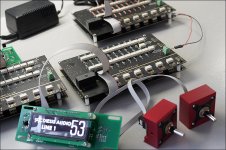
@Hicoco - Thanks. I'm using a Khozmo attenuator I haven't seen on their website. It was recommended by Arek (Khozmo proprietor) for my first DIY preamp and I really liked the way it worked, so I bought another one for this project.
In my first preamp, I did not have an input buffer, so fed the input directly to the attenuator (which operates in shunt mode). Since I didn't want too low an input impedance, I used a 20K series resistor. That one was built with Takman REX shunt resistors and Vishay Z-foil series resistor.
For this new preamp, I have added an input buffer so I could increase the preamp input impedance and decrease the attenuator resistance. I also decided to try different resistors, so this one will use Takman REY shunt resistors and AudioNote Silver Tantalum Non-Magnetic 4.7K series resistor.
The attenuator includes a 6-to-1 input selector, two rotary encoders (one for selecting input and one for volume), an OLED display, and an IR remote control.
Each attenuator PCB can support two channels, but the boards can be sandwiched with a daisy-chained control cable to support more channels.
I've included a photo from Khozmo as well as a photo of my first DIY preamp.
- Jay
Attachments
You are welcome. A very nice fully kitted out build. That spiral "shield" signal cabling technique I have seldomly seen only from some UK technicians. Interesting to see it in your builds.
Salas, is this better you think then twisting signal and return together?
nash
For this new preamp, I have added an input buffer so I could increase the preamp input impedance and decrease the attenuator resistance. I also decided to try different resistors, so this one will use Takman REY shunt resistors and AudioNote Silver Tantalum Non-Magnetic 4.7K series resistor. - Jay
Hi Jay,
Thanks for the info on the umbilical.
What kind of buffer stage are you adding? You really feel it will help since practically speaking in your normal listening attenuation position I dont think the output R of the attenuator is of much significance. Also will have its own signature.
I am using Shinkoh tantalum and Takman REY shunt and I am sure you will be pleased.
nash.
What kind of buffer stage are you adding? You really feel it will help since practically speaking in your normal listening attenuation position I dont think the output R of the attenuator is of much significance. Also will have its own signature.
@nashbap - I'm using an AMB Labs alpha 24 with Vishay Z-foil resistors. I don't know for sure that it will help, but my Denafrips Terminator+ DAC has an output impedance that is fairly high (1250ohm) and Salas recommends a 5K source impedance, so I felt that trying to go passive into the attenuator would be pushing my luck.
I used this same buffer stage as the output stage in my current preamp and it sounds very nice. The combination of the Khozmo attenuator and the alpha 24 sounded much better in my system than the Parasound JC2 preamp I had been using. I'm hoping (expecting) that the two chassis power supply with Ubib regulators, combined with the DCG3 for the gain/output stage, will be further improvement.
Salas, is this better you think then twisting signal and return together?
nash
Nash hi
Different things. Twisted is self canceling thus low inductance. Rate of twist should be smaller than the EMI wavelength to be avoided. Shielding is blocking and draining.
Spiral is an easier way of shielding for mechanical flexibility and hand making but not effective up to RF like tightly braided or foil shields in ready made cables. Due to its higher inductance because coiled.
Twisted is at best with carrying differential signals in a weak RFI environment. Shielded is better effective in single ended weak signal higher EMI environment.
A shield can additionally be applied to twisted pair for RF protection and separation from neighbor pairs like in shielded UTP.
For a balanced DCG3 preamp fed by ubibs, how much VA should the trannies be?
I can get 60VA r-core 20V.
I also have 2 120VA selectronics r-core 24V laying around, would that be pushing the ubibs to much?
regards,
John
I can get 60VA r-core 20V.
I also have 2 120VA selectronics r-core 24V laying around, would that be pushing the ubibs to much?
regards,
John
50VA each is enough and you can use bigger. Higher than necessary AC voltage pushes the heat dissipation on Ubib's M1. Asking for bigger sinks and more space or ventilation. Without strong side benefits. You can use 18VAC transformers but not lower.
Hi,
Is your 18 VAC but not lower recommendation for the UBiB only? I used dual 15 VAC for a different power supply and do not see any I'll effects from doing so. I seem to still be able to drop enough volts for the regulators.
Thanks,
Alan
Is your 18 VAC but not lower recommendation for the UBiB only? I used dual 15 VAC for a different power supply and do not see any I'll effects from doing so. I seem to still be able to drop enough volts for the regulators.
Thanks,
Alan
- Home
- Source & Line
- Analog Line Level
- Salas DCG3 preamp (line & headphone)