Here to say, Χρόνια Πολλά, Salas.
Best festive wishes to you and all this wonderful community.
Despite being horrible 2020, this year has brought me great diy highlights. Many of them, if not all, thanks to your expertise.
Back on topic, my only regret with DCG3 is that I don't have two of them

Thanks Siberia. Merry Christmas to all.
After three years of enjoyable listening with the DCG3 I recently feared that I had caused some serious damage, which resulted in distressing headphone noises. With limited troubleshooting skills, I feared the worst. While carrying the unit (sans cover) to my table in a dimly lit room I noticed that one of the led bars remained lit (from stored capacitance I presumed) and that its related MJE sink was cold relative to the others. I soon realized that while rearranging my audio components, I had inadvertently pressed down on the DCG3’s top cover, causing it to come in contact with the MJE sinks (and possibly other parts). A new BC550 and sink insulators made for a surprisingly quick fix, and I’m back in the saddle. Bottom line…those arrays are more than pretty lights🙂
While I had the hood up I changed out the split bobbin transformers for quieter toroidal types, and rechecked offset. It’s now back in the center of my modest but enjoyable system. Thanks for a terrific bit-o-kit Salas, and for the work you do to make ‘the good stuff’ accessible to the rest of us.
Keith
Nice quick fix Keith. Saved by the lights indeed. You are welcome.
dcg3 as opamp for dac output bAL to SE output.
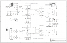
attached is the «IanCanada» dac output for sabre. The one in my topping d10s 9es3038q2m has the same topology but with different opamp and slightly different resistor values (about double the values for opamp network) and i would have to desolder the capacitors to know their values. The last opamp is the one i'd like to swap for dcg3. So the gain that opamp sees is between 2 and unity....could this be a problem? i will measure the already in there feedback cap soon... but i guess i could just extrapolate the value from dcg3 guide....
cheers and merry christmas to everyone of course 🙂
Has to be utilized like an op-amp cell with + - inputs, meaning open access to its feedback return node. Following established balanced to SE op-amp arrangements as described in technical articles.
I don't know if it would react badly or not, never had a reason to try it like that. In such a case I would have kept the rearranged networks impedance as low as in its standard application at least.
attached is the «IanCanada» dac output for sabre. The one in my topping d10s 9es3038q2m has the same topology but with different opamp and slightly different resistor values (about double the values for opamp network) and i would have to desolder the capacitors to know their values. The last opamp is the one i'd like to swap for dcg3. So the gain that opamp sees is between 2 and unity....could this be a problem? i will measure the already in there feedback cap soon... but i guess i could just extrapolate the value from dcg3 guide....
cheers and merry christmas to everyone of course 🙂
Attachments
Last edited:
ok thanks.
Opamp choice is not really critical(from earlier posts) is that correct...? What would be the main desirable carateristics of a good dc servo opamp?
Don't want to make «princess», but ad823 is not that cheap.... would opa1656 do it? my dac uses it already as i/v . they are low noise, cmos input, but smd. I don,t mind a bit of dc offset.
https://www.ti.com/lit/ds/symlink/o...45034&ref_url=https%3A%2F%2Fwww.google.com%2F
Last edited:
High input impedance (FET input opa) low offset low noise are desirable characteristics. OPA1656 works fine as U1 servo chip in DCG3. I have tested it.
I don't know if opa1656 will be cheaper as i can't see a dip version. You need a soic to dil adaptor. 😕
PS ok even then will be cheaper...
PS ok even then will be cheaper...
Last edited:
Salas finally got my opa1656 built correctly. I concur with your assessment on #4974. It is lean but has more inner detail. Going to listen for awhile, then switch back. Thanks for all your help,Mark
Hey Mark, great to know you got it up and running again. For assessment of a possible favorite new gen servo chip we will be happy to know about your further auditions and standard AD823 BOM chip comparisons opinion. In other words what characteristics count more for you in your system with your favorite music across more listening sessions.
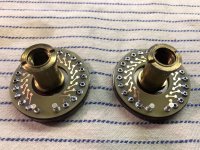
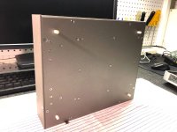
I've been on vacation for two weeks and have been working frenetically on packaging my preamp. It's close, but will be a week or two before it's finished. I think you will like the result.
Here's a sneak preview. I'm building up a 20K Daven attenuator. I decided to use SMD resistors. I built this today; it was a lot of work.
-Henry
Here's a sneak preview. I'm building up a 20K Daven attenuator. I decided to use SMD resistors. I built this today; it was a lot of work.
-Henry
Attachments
Interesting and involving diy work. It will be nice to see the end result soon. Wishing a much healthier and luckier 2021 for all.
Thank you, Salas, and the same to you. I've enjoyed playing with your circuit. I must have over a hundred hours in this project by now. Everything always takes so much more time (and money) than I expect at first, LOL. I have limited machine tools, so chassis work is a challenge.
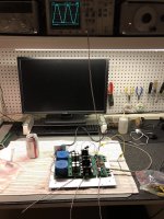
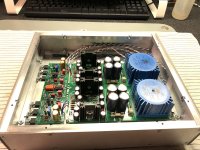
Here's a few more pictures.
It's interesting (to me) that the output can swing to the positive rail. I'm used to thinking in terms of bipolar cascodes so I was surprised the first time I saw it clipping at +17V on the scope. Not that it matters for headphone use, but I'm curious if you measured the distortion when M2 saturates.
-Henry
Attachments
uPA68H vs LSK389
Salas... I read, somewhere in the first few posts, that you tested both devices, but prefer the uPA68H. I think that today, it would still be true. Do you agree? Boards are on the way, and I must gather the necessary components. But there are over 5K posts to the thread, it is impossible for me to read them all.
Salas... I read, somewhere in the first few posts, that you tested both devices, but prefer the uPA68H. I think that today, it would still be true. Do you agree? Boards are on the way, and I must gather the necessary components. But there are over 5K posts to the thread, it is impossible for me to read them all.
@Henry
I had but I did not keep it on file. It was something like a series of harmonics -80dB bellow the 1kHz fundamental when just before clipping. Clipping level wasn't exactly rail to rail but just a little below if I also remember correctly.
Nice heavy metalwork by the way.
I had but I did not keep it on file. It was something like a series of harmonics -80dB bellow the 1kHz fundamental when just before clipping. Clipping level wasn't exactly rail to rail but just a little below if I also remember correctly.
Nice heavy metalwork by the way.
- Home
- Source & Line
- Analog Line Level
- Salas DCG3 preamp (line & headphone)