Having two 10k summing resistors at the sub's filter already just tap from the line out RCAs to another parallel output RCAs set.
No need for any additional buffer resistors to the new RCA then?
Salas got around building new offset ic today. Plugged it in with inputs shorted and meters on output. Got meters pegged when I turned it on. Pulled the ic. Turned back on to warm up and zero back out then install ic. Covered with towel to block drafts then went to eat supper. When I returned left channel fuses were blown. Replaced fuses. Got + and- 17 volts output on dcbs. But I have no dc offset in that channel on dcg3. Even when I adjust the pot. What happened and how do I go forward? Thanks mark
Attachments
Wrong orientation with the new chip? Could it have killed J1-J2? Compare DC voltages at points around J1-J2 & Q1-Q2 to the good channel.
After I pulled the opamp I had 50mv dc in one channel going down which is normal and 150 my dc in the other going down. A little high to start. When I covered with towel to go eat I had - 3mv and 10 mv in the other. When I came back the one channel fuses were blown.
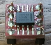
Soldered same as yours . Side with 1 and 8 facing relay like yours. Cleaned with alcohol before inserting. Residual alcohol left and shorted?
It does not have many active components. If something was upset or blown in the input stage it may have also dragged down Mosfets. Compare DC voltages around small and big active components pins to the good channel.
Soldered same as yours . Side with 1 and 8 facing relay like yours. Cleaned with alcohol before inserting. Residual alcohol left and shorted?
What pin is pin 1 on your adapter board? Maybe different?
Confirm pin 1 with continuity buzzer. If correct, the SMD chip can be also killed during soldering due to overheating or static.
Incidentally I was at katopis today where he happily demoed OPA2156 and OPA1642 to me installed in his balanced build. Two chips at a time. He bought them assembled from a guy on eBay. He was swapping them without adjustments. Only by powering down. 0.000V offset in all goes. He was very excited with doing such chips comparisons.
Incidentally I was at katopis today where he happily demoed OPA2156 and OPA1642 to me installed in his balanced build. Two chips at a time. He bought them assembled from a guy on eBay. He was swapping them without adjustments. Only by powering down. 0.000V offset in all goes. He was very excited with doing such chips comparisons.
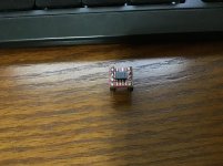
The line/bar on the opamp needs to be oriented with the dot on the DIP 8 board—assuming that white dot isn't some photo artifact. Opamp needs to be flipped. (Sorry.)
I think I can also now see a part of "2" mark near there. Sadly something went wrong for a reason. As for the chip itself it can be blown off with hot air gun and reinstalled.
Those ready made ones he showed me were TSSOP8 even tinier package on black adapters with gold pins. Most possibly installed with solder paste and hot air.
Isn't a bad idea to also mark pin 1 adapter's corner with a black felt pen if not strongly stated.
Pfarrell PIN number one with the square around it is front right with the opamp stripe on that side. Pin 8 is front left. Isn’t that the correct orientation?
Yes pin 1 is the square for socket orientation, but the traces rotate 90 to opamp orientation which is why they give you the registration dot on the top. notch, detent, line, depending on opamp abuts/orients to dot. Point is there's no directly aligning the notch, detent, line on opamp with pin 1 on the board—that's just for knowing orientation in the socket.
I made 2 of these faulty boards and my preamp doesn’t work now. Not feeling to good about my abilities now. Insert sad face here
- Home
- Source & Line
- Analog Line Level
- Salas DCG3 preamp (line & headphone)