I attached one ground wire (nearest one to mains ground first) and that had continuity to ground but upon probing the other side I found no continuity there, hence the second wire.
If all is silent then I'll probably leave well alone.
The idea is to bring the chassis at same zero level with the PCB zero level, which is normally the same between channels anyway, so it behaves like a box shield but also not to create a loop so you will judge by the result.
Well, a huge" PHEW" as all is working as Salas intended. Everything on and the volume up high, I have silence from the speakers (well almost). Pop a CD in and the sound is quite superb, very smooth with nothing sounding harsh or overemphasized. I have yet to try it in my house system and also with my DAC and M-scaler in the workshop. I am very much looking forward to future tests.
As I have no doubt you realised, I'm no EE but with the help and guidance from experienced builders, I can get there in the end. Many thanks to Mr T for putting the kits together and Salas for helping me through this build.
Edit: If I had created a loop would it mean some sort of hum from the speakers without music being played, at the moment it is the quietest I have ever heard from my EVO4 speakers.
Last edited:
So far so good. Congrats. Let us know how it will go with the other systems. Yes, a ground loop would bring humming and buzzing noises.
Noob question here.
I am back to the hobby after 5 years of hiatus. I have built several components, pre, power amp and speaker. However I just followed rules and that's all.
I have old boards named salad sslv 1.1 back in black. Can I use them to power DCG3 or I need DCSTB kit too?
I am back to the hobby after 5 years of hiatus. I have built several components, pre, power amp and speaker. However I just followed rules and that's all.
I have old boards named salad sslv 1.1 back in black. Can I use them to power DCG3 or I need DCSTB kit too?
DCG3bal now with UltraBib
Just an update that I have finally replaced the DCSTB in my doubled up balanced DCG3 with the Ultrabib power supply.
Honestly, I cannot detect too much of a difference. Violins seem a bit more fleshed out and the overall tonality slightly more musical. I experimented with voltages ranging from 15 to 17.5v and as with the DCSTB I have a slight preference for a lower voltage. I have settled at 15.5v as of now. The DCG3 has the Diotec 327 and the UPa's replaced with 2SK170's.
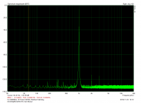
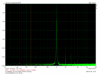
Attached are THD scans with DCSTB and with UltraBIB. With the Ultrabib's I had to mount the transformers on their sides as opposed to lying flat. They are however in the same location, one at each end of the case.
As expected, the Ultrabib is a no fuss, well designed performer with clearly labelled and well laid out boards.
Thank you Salas and TeaBag.
Nash
Just an update that I have finally replaced the DCSTB in my doubled up balanced DCG3 with the Ultrabib power supply.
Honestly, I cannot detect too much of a difference. Violins seem a bit more fleshed out and the overall tonality slightly more musical. I experimented with voltages ranging from 15 to 17.5v and as with the DCSTB I have a slight preference for a lower voltage. I have settled at 15.5v as of now. The DCG3 has the Diotec 327 and the UPa's replaced with 2SK170's.
Attached are THD scans with DCSTB and with UltraBIB. With the Ultrabib's I had to mount the transformers on their sides as opposed to lying flat. They are however in the same location, one at each end of the case.
As expected, the Ultrabib is a no fuss, well designed performer with clearly labelled and well laid out boards.
Thank you Salas and TeaBag.
Nash
Attachments
For the positive I used a 1r NS02B1R000FE12 and for the negative side I paralleled two 3.3r MRS25000C3308FC100. The positive M1 runs around 120F after a couple of hours with the lid closed, ambient 78F. I measured the case bottom at 105F.
Please see the pic that shows the transformers. I angled them slightly relative to each other. Is it acceptable to mount them this way? I tried putting one flat and one vertical but it proved very tight. In your experience what is the best positioning for two transformers in the same case?
Thanks. Nash
Attachments
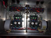
On your second FFT screenshot I see some previously low level harmonic spikes are cleared now so keep those transformers mounted that way as they give no traces of interference anymore. Reflecting on your THD+N figures. In a balanced build the PSUs are seen common mode and rejected better. From very good to excellent PSU the distance shortens. More audible when in SE builds.
Hi,
The amp is now rather finished. Here are a couple of pics of the whole thing and of the selection board.
Nice sound from the simple mp3 player connected so far.
Problem I am now facing: noise from the not connected inputs.
The noise is not present when the source-device is powered on, but the noise is there when the source-device is off.
The noise follows the position of the potentiometer/volume (increased volume=increased noise).
As seen in the whole picture, the GND of the DCSTB power-input is not connected to the chassis (green/yellow wire, red circle). Making this connection has only a little effect on the noise.
Touching the heatsink or the top of the capacitor of the i-select circuit increases the noise (X marks). In fact mostly when touching the top of the capacitor (similar to the noise that appears when touching the signal input).
The output connector receives only one screen (R+L+ground); connecting both screens has no effect on the noise.
The chassis is connected to the power ground next to the power connector; transformers ground are connected to the chassis (G marks).
Signal grounds and ground of the DCSTB power-inputs are connected together (but not to the chassis).
The power wire (from switch to transformers) is not screened.
Edit: the front panel is made of plexi, not metal.
Hope someone can make something out of this info.
What happens if you will connect selector's 0V power line with signal GND? Also connect the pot's metal body to chassis.
The pot's metal body is already connected to the chassis through its L-shape support screwed to the box (maybe not clear in the pic).
Will try the 1st connection you proposed: i-select 0V with signal ground.
Will try the 1st connection you proposed: i-select 0V with signal ground.
What happens if you will connect selector's 0V power line with signal GND?
Before to make mistakes, do you mean the 0V of the DCin connector? 😱
Tried that: it did not kill the noise, something like 9V between selector-0V and the signal ground, D3 of the selector is now smoking when powering on the amplifier.
The selector is powered from one secondary of the top transformer (small grey cable in the above picture).
- Home
- Source & Line
- Analog Line Level
- Salas DCG3 preamp (line & headphone)