gnat_leader said:Btw, personally I'd rather pay some small fee.. say $25 for the plans and know they will be spot-on. It's worth it to me not to waist the time. So Dave/Ron... perhaps there's potential here. You guys could make a few bucks and get duely compensated for your efforts! ;-)
People are making donations... a "bribe" like that can rearrange the queue.
I think you are probably the 1st person to do the side firing version.
dave
Good point. I'll ping the other two guys for kicking in some bucks for a donation... We are building 3 pairs of the side firing config. Will post pics when finished. First (trial) pair is almost together ... just raw plywood... to be nicely veneered later if we like what we hear.
Dave, what differences did you hear once you modified the 126 driver (Mod Podge on the cone)? Did the treble quantity/quality diminish at all?
gnat_leader said:Dave, what differences did you hear once you modified the 126 driver (Mod Podge on the cone)? Did the treble quantity/quality diminish at all?
The top end is much smoother, much of (but not all -- at least yet*) of the HF peakiness removed. Noise floor is reduced allowing greater downward dynamic range.
Florian has identified what we think is a remanent of these at about 6 k. Not masked by others he is finding that is stands out. Anyone suggest a starting point for a notch filter to see if that can help?
dave
Thanks Dave. Really appreciated.
Alternatively -- as I posted this question in the other forum -- it would be good to know if there are any full range replacements for the FE126 we can try (i.e. similar size, Fs and Qts but -- ideally -- smoother and more extended).
Thanks again,
Florian
Alternatively -- as I posted this question in the other forum -- it would be good to know if there are any full range replacements for the FE126 we can try (i.e. similar size, Fs and Qts but -- ideally -- smoother and more extended).
Thanks again,
Florian
We are just now trying FF125 in the Frugel-Horn... specs are almost exactly the same as the FE126
dave
dave
planet10 said:We are just now trying FF125 in the Frugel-Horn... specs are almost exactly the same as the FE126
dave
thanks for the nudge - I'll have to dig out the soldering iron tonight
Is the notch at 6.5Khz a positive?(FR curve talking here)
ron
Just looked at the FR graph, angle the drivers 15 degrees off axis from the listener position. Now you need a wide dispersition tweeter rolled in at around 7.5Khz.
ron
Just looked at the FR graph, angle the drivers 15 degrees off axis from the listener position. Now you need a wide dispersition tweeter rolled in at around 7.5Khz.
7.5 Khz first order. Howevr if phase correction is desired then the plane of the energy production of the tweeter will have to be closer to the listening (target point) position by .45" than the VC of the A126.
ron
(from my tech postings in the FR forum)
I really dont feel well at the moment but i wanted to post this. I really should post this in a white paper but i am not up to it at the moment.
On the subject of plane alignment of transducers at crossovers.
1. This is an evaluation of first order crossovers at a 90 deg phase change.
2. This is an evaluation of physical plane (vertical plane placement) of the energy producing points of two transducers.
3. This has impact on the order of wave points ( ie: points on a sine wave) and the time /distance of the arrival of the wave points to a given greater position.
If you look the given general concensus is that adding a first order crossover will give a 90 degree phase change. This means that the secondary transducer will see the signal at a later time than the first. The time that the second transducer will see the signal is based upon the V of the signal transfer circuit plus the added phase differential. I am not going into the " speed of electronic conductance" as this means very little in audio.
Given that at a 90 deg. phase difference that the signal will become effective the distance is:
dis=(V/F)/4.
where: dis= distance
V= velocity of the medium
F=frequency in Hertz
This is fairly simple as at 1/4 wavelength it is a 90 degree phase change. So the time/distance of the phase change is dependant on the velocity of the medium ( air) and the frequency.
Conclusion: Proper placement of the transducers in respect to the listener position should be taken into account for the difference for the phase point of the added delay of first order crossovers. Physical alignments of the planes of energy production should be adjusted for the phase difference.
ron
ron
(from my tech postings in the FR forum)
I really dont feel well at the moment but i wanted to post this. I really should post this in a white paper but i am not up to it at the moment.
On the subject of plane alignment of transducers at crossovers.
1. This is an evaluation of first order crossovers at a 90 deg phase change.
2. This is an evaluation of physical plane (vertical plane placement) of the energy producing points of two transducers.
3. This has impact on the order of wave points ( ie: points on a sine wave) and the time /distance of the arrival of the wave points to a given greater position.
If you look the given general concensus is that adding a first order crossover will give a 90 degree phase change. This means that the secondary transducer will see the signal at a later time than the first. The time that the second transducer will see the signal is based upon the V of the signal transfer circuit plus the added phase differential. I am not going into the " speed of electronic conductance" as this means very little in audio.
Given that at a 90 deg. phase difference that the signal will become effective the distance is:
dis=(V/F)/4.
where: dis= distance
V= velocity of the medium
F=frequency in Hertz
This is fairly simple as at 1/4 wavelength it is a 90 degree phase change. So the time/distance of the phase change is dependant on the velocity of the medium ( air) and the frequency.
Conclusion: Proper placement of the transducers in respect to the listener position should be taken into account for the difference for the phase point of the added delay of first order crossovers. Physical alignments of the planes of energy production should be adjusted for the phase difference.
ron
Needless to say that the signal between the two transducers are out of phase till the XO point then they are in alingment, then as the first driver falls off in response the second picks up the signal. This makes a statement for the initial driver to be rolled off electronically and allow the slopes of the two to intersect at a given frequency and a given distance(lamda at a frequency) between the two centerlines of maximum energy.
ron
(ron gets on his soapbox) One of the greatest falts of the modern day commercial designs is time alingment IMHO. The second is baffle step comepensation. They design around very skinny tall cabs which are visually acceptabe according to SAF but in electronically inducing a correction factor the components introduce a "sound" of their own. Then they introduce a multi driver assembly ,there is no compensation of the signal arrival time.
planet10 said:Florian has identified what we think is a remanent of these at about 6 k. Not masked by others he is finding that is stands out. Anyone suggest a starting point for a notch filter to see if that can help?
Based on the freq. measurements avail here and on the measurements in the thread on Dave's FE126 mods I am targeting for a parallel notch with -3 dB at 6kHz and 7kHz and 9 dB attenuation.
Simple calculator here
Oppinions ? suggestions ?
TIA,
Florian
I don't have much practical experience with notches, the help here says broad adjustments, and i note that the calculator gives the same results for 5 dB as for 1 dB. (i used 6,2k & 7.1 k based on Trol's graph)
A series notch filter in parallel with the driver might have greater specificity, but the calc on that site assumes you are dealing with a fundemental resonance.
Also keep in mind that the peak on the modified driver is likely not as severe as what Trols shows (my measures are problematic (has to do with the mic i used)). The impedance curves show a reduction in the primamry resonances bump.
dave
How NOT to add the SB
Dave, many thanks -- with some delay -- for the input on the notch filter. I'll dig more into it as time permits.
In the mean time I've been (too) slowly working on adding an SB to the horn. (Very) unfortunately this was a bit misguided mod, so this is kinda "how NOT to do it".
First, many apologies to Ron are in order. I should have know he must have thought about this ....
It all boils down to the misguided belief (read on several posts, some by Ron himself) that the backof the driver should be obstructed as little as possible in order not to obstruct the back wave. As such I thought that front mounting the driver on the front baffle (well, not much choice there) was less then optimal since the back wave is laterally "obstructed" for a depth equal to the thickness of the front baffle.
Consequently I thought it would be better if I would remove that obstruction by rear mounting the driver on the SB and do a cut-out in the front baffle.
I've started by cutting out the front baffle for a height just about enough to fit the whole driver frame (130 mm x 155mm cut-out i.e. the cut is for the whole width of the front baffle):
The SB consists of a stacked double layer of 18mm plywood.
The lower layer is friction mounted around the speaker (like Chris suggested above).
The lines above and below where the driver is mounted show where the cut-out in the front baffle fits -- not more then 3mm above and below the driver frame
The top layer of the SB has the driver cut-out and the edges routed at 45 degrees:
Driver rear mounted and ready to go (I added the dowels for extra bracing/fit. The front/upper layer of the SB comes flush, air-tighty with the speaker front baffle):
Everything mounted and playing:
Why it wasn't such a good idea: The speaker is much leaner, a bit too much actually. It sounds "thin". Yes, it's the bass seems "faster" but now it does sound like coming from a 4''er. In frequency terms the output around the critical 100 Hz region is reduced considerably
Not sure if the reduced horn action is due to the added CC volume (removing that 130mm x 155mm adds a volume of 0.362 liters to the CC volume, already at 2.1 liters) or the fact that what now consists the front baffle wall has a 18 mm "step". Anyway, it sure was better with driver mounted as it was before.
I've experimented very briefly with stuffing the CC with wool felt (yes Ron, I know you don't approve CC stuffing, just had to try it) but it didn't make any significant differences.
The worst part of it is that now the whole balance of the speaker is lighter and the aforementioned peak in the treble even more distinguishable.
So, any suggestions how to fix this ? My obvious next move would be to try to mount back the front baffle cut-out around the driver and glue that to the back of the SB such that to regain as much as possible of the original CC shape and volume. Any other suggestions are welcomed
Florian
P.S. The SB dimensions are exactly like Ron posted above: Squared, 30 cm. The SB itself does it job and fills in the 250Hz region nicely (didn't had a sine of exactly 260 Hz around).
Dave, many thanks -- with some delay -- for the input on the notch filter. I'll dig more into it as time permits.
In the mean time I've been (too) slowly working on adding an SB to the horn. (Very) unfortunately this was a bit misguided mod, so this is kinda "how NOT to do it".
First, many apologies to Ron are in order. I should have know he must have thought about this ....
It all boils down to the misguided belief (read on several posts, some by Ron himself) that the backof the driver should be obstructed as little as possible in order not to obstruct the back wave. As such I thought that front mounting the driver on the front baffle (well, not much choice there) was less then optimal since the back wave is laterally "obstructed" for a depth equal to the thickness of the front baffle.
Consequently I thought it would be better if I would remove that obstruction by rear mounting the driver on the SB and do a cut-out in the front baffle.
I've started by cutting out the front baffle for a height just about enough to fit the whole driver frame (130 mm x 155mm cut-out i.e. the cut is for the whole width of the front baffle):
An externally hosted image should be here but it was not working when we last tested it.
The SB consists of a stacked double layer of 18mm plywood.
The lower layer is friction mounted around the speaker (like Chris suggested above).
The lines above and below where the driver is mounted show where the cut-out in the front baffle fits -- not more then 3mm above and below the driver frame
An externally hosted image should be here but it was not working when we last tested it.
The top layer of the SB has the driver cut-out and the edges routed at 45 degrees:
An externally hosted image should be here but it was not working when we last tested it.
Driver rear mounted and ready to go (I added the dowels for extra bracing/fit. The front/upper layer of the SB comes flush, air-tighty with the speaker front baffle):
An externally hosted image should be here but it was not working when we last tested it.
Everything mounted and playing:
An externally hosted image should be here but it was not working when we last tested it.
Why it wasn't such a good idea: The speaker is much leaner, a bit too much actually. It sounds "thin". Yes, it's the bass seems "faster" but now it does sound like coming from a 4''er. In frequency terms the output around the critical 100 Hz region is reduced considerably
Not sure if the reduced horn action is due to the added CC volume (removing that 130mm x 155mm adds a volume of 0.362 liters to the CC volume, already at 2.1 liters) or the fact that what now consists the front baffle wall has a 18 mm "step". Anyway, it sure was better with driver mounted as it was before.
I've experimented very briefly with stuffing the CC with wool felt (yes Ron, I know you don't approve CC stuffing, just had to try it) but it didn't make any significant differences.
The worst part of it is that now the whole balance of the speaker is lighter and the aforementioned peak in the treble even more distinguishable.
So, any suggestions how to fix this ? My obvious next move would be to try to mount back the front baffle cut-out around the driver and glue that to the back of the SB such that to regain as much as possible of the original CC shape and volume. Any other suggestions are welcomed
Florian
P.S. The SB dimensions are exactly like Ron posted above: Squared, 30 cm. The SB itself does it job and fills in the 250Hz region nicely (didn't had a sine of exactly 260 Hz around).
With a CC volume of 2.46 liters you have drastically reduced the horn action. Which is why i quoted a 2.2 liter with the sized baffle as they worked hand in hand to balance the XO point. What you have now is a highly tuned BR with the vent firing into a horn expansion. Adding woll may just give the effect of an even larger CC. I would not be surprised that at somewhere between 180-240 Hz there is excessive cone movement.(loss of loading)
Install a wooden block that will reduce the CC volume to 2.2 liter. Or better yet several small wooden sphers at the rear of the cc at the angle point.
ron
Install a wooden block that will reduce the CC volume to 2.2 liter. Or better yet several small wooden sphers at the rear of the cc at the angle point.
ron
ronc said:Install a wooden block that will reduce the CC volume to 2.2 liter. Or better yet several small wooden sphers at the rear of the cc at the angle point.

Will do asap. Thanks (yet again...) ron. It's amazing how such a change can do to the character. But then again, you were referring to 1 degree changes in the flare, so...here's for living in the world of exacts

Florian
Now. Where was that wooden necklace my wife has ?!?...
I have no idea if there are Hobby Lobbys there. Its one of the places i haunt. There are all kind of craft things that can be applied to DIY audio. I still dink with the Estes mdl rockets there.
ron
ron
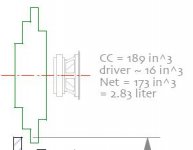
Net CC volume 2.2l with FE126 or?
Hi, I just have a short question regarding the CC volume.
Basically, Is the driver volume included in the total volume, or should the CC be extended with the driver volume to achieve net 2.2l?
I guess that Ron, who designed this horn is the only one, who could tell. I have attached an example with a snapshot from the mikasa spawn series, where the driver volume for FE126 is stated.
Anders
Attachments
Trying to recreate A126 rev H on cad
Thank´s for your reply Ron, I have used your info regarding the CC as well as the existing gif-files as indata for a cad-version of this speaker.
I think I am pretty close now and i am also going to build a set in the near future.
The drawing is based on 0.72 ply, we use 18mm ply in Sweden (which is actually 17.7 mm nominal). I will make a version of this one as well, as the difference will affect the depth with a couple of mills.
Anders
Attachments
- Status
- Not open for further replies.
- Home
- Loudspeakers
- Full Range
- Rons Austin A126 for the metric freak newbie