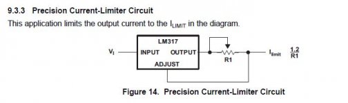
If you don't have current limiting available, consider making one. Takes only two components. See paragraph "9.3.3 Precision Current-Limiter Circuit" in this PDF:
https://www.ti.com/lit/ds/symlink/lm317.pdf
And revisit my post 119--- I was editing while you posted. That Max Smart thing you mentioned earlier. 😉
My bitter story was about trying to attach hookup wire test points to SMT part leads without careful stress-relief. I've ripped traces of the board--- more often than once. If I'm less than reckless, I attach with #30 wire wrap wire anchored somewhere safe.
https://www.ti.com/lit/ds/symlink/lm317.pdf
And revisit my post 119--- I was editing while you posted. That Max Smart thing you mentioned earlier. 😉
Care to share your bitter story about measuring vRegs? It might help
keep me or Everyman who is following along from the same fun.
My bitter story was about trying to attach hookup wire test points to SMT part leads without careful stress-relief. I've ripped traces of the board--- more often than once. If I'm less than reckless, I attach with #30 wire wrap wire anchored somewhere safe.
Last edited:
Steve,
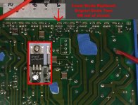
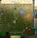
Yes I understand. I was concerned about tacking on to a small SMD point, thinking
it's pretty simple to lift that off the board. So my primary ground connections
is on that Cap10 Neg Terminal.
Another Post is attached to Cap 14 Neg terminal.
Caps 15, 16 filter primarily vReg 5 and vReg6, with a cross over
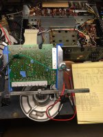
to vReg4. By studying that back lit board, I can see the small ground
references tie-ing the first six of 10 vRegs together.
Then there is that middle bridge rectifier on it's own island.
Continuing on up 7, 8,9,10.
Across the top, on right are the four bridge rectifiers and
Six series vRegs.
The last three, vRegs 4, 5, 6 go off board somewhere,
supplying off board.
Slowly the light has increased another few lumens.
I'll get back on it later or early am.
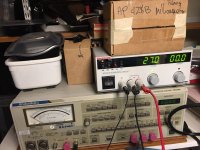
Yes, my lab supply has current limiting, but the limit pot LEDs
only say something if they are limiting, other wise they have
zeros. I think they are actually the flat panel number rectangles
with seven segments? I could be wrong.
I'll take a pic of it. As I can't dial anything in unless it is limiting.
So I just keep it turned low, or high enough so i can read the output
voltage.
Cheers,
Post Script - I'll be, and yes I was calculating that for some project I was doing, not for class, but for something
and I was calculating 1.2/R1 for a long time. I also recall placing a small load resistor at the output so that
I wouldn't zero ohm the pot and fry the LM317. Or make is oscillate etc.
Now I'm trying to recall what I used it for.
Maybe in a small transistor matching jig that lost the my schematic and note for.
Then found and lost and found again.
Yes, that was it, the transistor matching jig using the Moog synth guys method for matching
then incorporating some of Bob Pease's components on the board to make is adjustable.
If I find the diagram in the book I'll post a pic, probably in the next post
as time is almost up for this post.
Yes I understand. I was concerned about tacking on to a small SMD point, thinking
it's pretty simple to lift that off the board. So my primary ground connections
is on that Cap10 Neg Terminal.
Another Post is attached to Cap 14 Neg terminal.
Caps 15, 16 filter primarily vReg 5 and vReg6, with a cross over
to vReg4. By studying that back lit board, I can see the small ground
references tie-ing the first six of 10 vRegs together.
Then there is that middle bridge rectifier on it's own island.
Continuing on up 7, 8,9,10.
Across the top, on right are the four bridge rectifiers and
Six series vRegs.
The last three, vRegs 4, 5, 6 go off board somewhere,
supplying off board.
Slowly the light has increased another few lumens.
I'll get back on it later or early am.
Yes, my lab supply has current limiting, but the limit pot LEDs
only say something if they are limiting, other wise they have
zeros. I think they are actually the flat panel number rectangles
with seven segments? I could be wrong.
I'll take a pic of it. As I can't dial anything in unless it is limiting.
So I just keep it turned low, or high enough so i can read the output
voltage.
Cheers,
Post Script - I'll be, and yes I was calculating that for some project I was doing, not for class, but for something
and I was calculating 1.2/R1 for a long time. I also recall placing a small load resistor at the output so that
I wouldn't zero ohm the pot and fry the LM317. Or make is oscillate etc.
Now I'm trying to recall what I used it for.
Maybe in a small transistor matching jig that lost the my schematic and note for.
Then found and lost and found again.
Yes, that was it, the transistor matching jig using the Moog synth guys method for matching
then incorporating some of Bob Pease's components on the board to make is adjustable.
If I find the diagram in the book I'll post a pic, probably in the next post
as time is almost up for this post.
Attachments
Last edited:
Taking a little break, doing some measurements before I rebuild, upgrade, recap,
relight, refurbish, replace all the stuff that is known to fail with better stuff, etc in
a little receiver I got for my little girl for her 8th birthday. It will be a legacy amp
for her, and when I'm gone, she'll listen to music on it etc. It's not bad right now
but at 50 years old, the little Marantz 2230 needs some TLC. She's a great kid,
loves life, loves music too. It will help her to keep focused with her own music
and her music lessons, etc, her art now and in the future.
I'll be back in a day or two after this refresher. I just want to get the measurements
done to compare before and after.
Cheers,
I remember when my son was eight. I blinked my eyes and he's forty.
Your priorities are in the right place.
Your priorities are in the right place.
electronic & Steve, Yes and yes.
Besides hanging out with her, I also want her to know later in her life
that I did specific thing just for her, because its a gift of love from Dad.
I'll get back on the UPD soon, too.
Cheers,
Besides hanging out with her, I also want her to know later in her life
that I did specific thing just for her, because its a gift of love from Dad.
I'll get back on the UPD soon, too.
Cheers,
UPDATE:
Did a quick diode test on the diode I removed and replaced.
From the diode check function on HP34401A, it passes the
test both ways, showing .531Vdc and open going the other way.
So, perhaps the issue is the vReg. I'll have to find some vRegs
that I have stashed and compare them with transistor checker if that
works, or build test jig based on data sheet information.
It shouldn't be a big deal to pull and remove as its on a heat sink pad.
I'm wondering if the standard type tests would reveal anything.
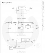
Original Plan to follow LM317 Test series:
1. Line Regulation Test circuit
2. Load Regulation Test circuit
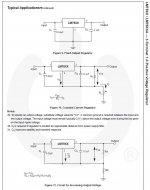
3. Standard Test Circuit
4. Ripple rejection Test Circuit
These look to be the series of tests from National/On-Semi.
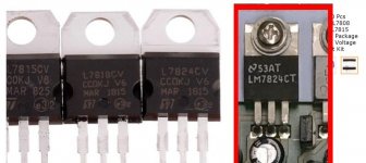
Recall this is for the vReg designated as #6 on the 10 vReg heat sink.
it is the LM7824, configured as: 1. Input 2. GND 3. Output.
However the LM7824 Tests are slightly different.
Did a quick diode test on the diode I removed and replaced.
From the diode check function on HP34401A, it passes the
test both ways, showing .531Vdc and open going the other way.
So, perhaps the issue is the vReg. I'll have to find some vRegs
that I have stashed and compare them with transistor checker if that
works, or build test jig based on data sheet information.
It shouldn't be a big deal to pull and remove as its on a heat sink pad.
I'm wondering if the standard type tests would reveal anything.
Original Plan to follow LM317 Test series:
1. Line Regulation Test circuit
2. Load Regulation Test circuit
3. Standard Test Circuit
4. Ripple rejection Test Circuit
These look to be the series of tests from National/On-Semi.
Recall this is for the vReg designated as #6 on the 10 vReg heat sink.
it is the LM7824, configured as: 1. Input 2. GND 3. Output.
However the LM7824 Tests are slightly different.
Attachments
IIRC, we suspected connection of the regulator's ground/adjust was established at the destination module.
I believe you've had DC volts applied successfully to the bulk caps without any smoke; I suggest repeating this configuration. Connect DVM black lead to bulk cap ground lead and probe regulator Vin, Vout, and Vground. I suspect you'll find all three terminals are approximately equal to the applied bulk cap voltage. This is confirmation that reference connection is made at the destination board. Temporarily connect the reference terminal or reference resistor divider at bulk cap common and regulator should start (unless failed).
I believe you've had DC volts applied successfully to the bulk caps without any smoke; I suggest repeating this configuration. Connect DVM black lead to bulk cap ground lead and probe regulator Vin, Vout, and Vground. I suspect you'll find all three terminals are approximately equal to the applied bulk cap voltage. This is confirmation that reference connection is made at the destination board. Temporarily connect the reference terminal or reference resistor divider at bulk cap common and regulator should start (unless failed).
Grey magic smoke from the AT PSU today. Not a typical dark/blueish one.
Wondering if the B1 option from .02 is compatible with .05
Wondering if the B1 option from .02 is compatible with .05
Hi electronic,
I probably won't be any help to you--- I have no schematics nor any familiarity with these RS instruments. Do they have RS designed linear supplies to power the AT-based computer or do they use switchers akin to personal computers?
Does it make any sense to test/debug the computer with an old AT switcher? I don't know if this idea poses risks, so please get more knowledgeable advice before pursuing this perhaps insane notion.
Good luck!
So the probably obvious questions: RS sub-contracted the PC supply to a third party? Or is RS the OEM? Third party support available? Is the PC supply powered directly from the AC mains?
IIRC, we suspected connection of the regulator's ground/adjust was established at the destination module.
I believe you've had DC volts applied successfully to the bulk caps without any smoke; I suggest repeating this configuration. Connect DVM black lead to bulk cap ground lead and probe regulator Vin, Vout, and Vground. I suspect you'll find all three terminals are approximately equal to the applied bulk cap voltage. This is confirmation that reference connection is made at the destination board. Temporarily connect the reference terminal or reference resistor divider at bulk cap common and regulator should start (unless failed).
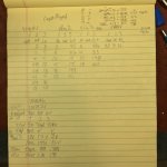
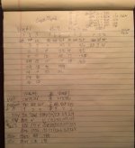
Hi Steve, almost.
However, on vReg #6, LM7824, the voltages were not the same.
It took two tries to verify this; initially through bulk cap #10,
was not correct as shown by raw data measurements.
Then hooking up through bulk cap #13. However the measurements
weren't correct either.
Supply = 30.0V
Pin1-in = 30.002V
Pin 2gnd = 2.18V
Pin 3 out = 1.98V
I think this demonstrates faulty vReg #6., LM7824CT.
I can try to hook up a load through the flex cable.
I'd use a 12V automotive lamp, dual bulb, for 24Volts.
That would be 12V drive and w/12V brake light.
Lab is processing pics.
Cheers,
Grey magic smoke from the AT PSU today. Not a typical dark/blueish one.
Wondering if the B1 option from .02 is compatible with .05
electronic, Bummer. Is this the switcher which the analog power supply feeds?
Is this section of the UPD the "sample schematic?" Let me send that off to
Steve maybe that will be beneficial.
Cheers,
Last edited:
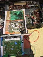
Here are the test pics along with test data to go along with post #133.
I sent Steve the Sample Schematic.
FYI - My comment about the power supply may not be accurate.
My next steps are to solicit buying a few of the voltage regulators over
in the Swap Meet Section. For just a few parts, buying through distribution
isn't cost effective.
Cheers,
I sent Steve the Sample Schematic.
FYI - My comment about the power supply may not be accurate.
My next steps are to solicit buying a few of the voltage regulators over
in the Swap Meet Section. For just a few parts, buying through distribution
isn't cost effective.
Cheers,
Attachments

Last edited:
Did you check Amazon? https://www.amazon.com/BOJACK-Packa...jbGlja1JlZGlyZWN0JmRvTm90TG9nQ2xpY2s9dHJ1ZQ== I would send you one regulator but it would cost me what they charge for the kit.
They also have negative regulator kits. https://www.amazon.com/Values-LM790...child=1&keywords=lm7924&qid=1617673625&sr=8-1 Delivery midweek.
Sync
Please humor me: retest Reg #1 with 27V applied. I assume you'll get the same data you reported earlier. Maintain the same connection of DVM- to "ground"and use DMV+ to measure the Reg #1 ground terminal at the body of the IC.
I'm predicting the observed voltage won't be ground!
Please humor me: retest Reg #1 with 27V applied. I assume you'll get the same data you reported earlier. Maintain the same connection of DVM- to "ground"and use DMV+ to measure the Reg #1 ground terminal at the body of the IC.
I'm predicting the observed voltage won't be ground!
Steve,
Humor you, oh my. You do know I don't have a sense of humor.
I'm the natural straight man.
However, do to circumstances and a promise not to be
escorted out of the comedy club, I shall provide humor.
Oh but it will. The observed Voltage will be ground.
Hang on there...ground potential rises up to approx input voltage.
Maybe that isn't really ground, but ground in this instance?
It would do this why? I'll guess, because that is the way
the board with these parts are configured.
I'll also go back and check the other vRegs as long as
I'm trying to be funny.
I think their grounds will also rise.
Am I thinking clearly, that because the ground voltage rises
with input voltage rise, the device is working properly.
However, for the vReg#6, it's ground and output voltages
did not rise because the vReg is faulty.
If i recall, vRegs 1 thru 3,
all had the GND tabs track the output/input voltage
as there is no load on these.
However, I live by the theory, trust but verify (which p-i-s-s-e-s some folks off) but then how do you know?
So I had the lab use their A.S.A.P. process for an extra fee.
I also verified what the max input Voltage was from the data sheet too,
it's 30V. I'll take a stab that this device is Adjustable because there are not
voltages listed on the case.
I didn't hook up the 12V +12V automotive lamp.
The data is attached.
Cheers,
Attachments
- Home
- Design & Build
- Equipment & Tools
- Rohde & Schwarz UPD: Troubleshoot then Restore to Glory