BJT Matching circuit troubles
All,
I've set up and measured Hfe for my NJL0281 transistors per the circuit in the build guide. I used a bread board, everything went smoothly and the numbers seem sensible to me.
However, when I set up the circuit to measure Hfe for the NJL0302, it doesn't seem to work. Here are the relevant voltages (all with respect to ground)
Power supply voltage: 15V
Vemitter of DUT (NJL0302) 15V (per the schematic)
Vbase of DUT 15V (i.e. no current flowing into base, thru 2k resistor)
Vcollector of DUT 0.3V
Vbase of MJE15030 1.03V
Vcollector of MJE15030 0.3V
Vemitter of MJE15030 0.3V
I have measured the hfe of the MJE device and it checks out (150)
If I pull the MJE from the circuit, then I get simply a series LED and 470R resistor, the LED lights up as it should.
Any ideas as to what I am doing wrong? It's not complicated. Again, it's on a bread board and I successfully measured the 0281 devices. I did rebuild the circuit (R6 in different position) per the builders guide for the the 0302 devices.
Thanks in advance.
Ryan
Andrew,
I wired it per the construction manual which doesn't have -15v on the supply. It does change the position of the bjt so the relative emitter and collector voltages changes from PNP to NPN.
I retreated and did the hfe testing as described here:
Transistor matching
I. e. with a passive network of resistors and all the measurements came out sensible i.e. Hfe in the 110 to 125 range. I can only guess that I had some bad connections on the breadboard that I was too impatient to find.
Thanks
Ryan
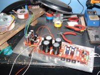
Finally i bought a infrared thermometer and i was able to measure my FC-100 temperatures.
At 26-27 celsius degrees heatsinks measure around 50 deg on outside.
Inside highest temp i measure on shunts for frontend a bit higher than 60 deg celsius.
Is not a bit too much ?
At 26-27 celsius degrees heatsinks measure around 50 deg on outside.
Inside highest temp i measure on shunts for frontend a bit higher than 60 deg celsius.
Is not a bit too much ?
It is perfectly normal. Mine is working without top cover in the summer and covered in the rest of the year 🙂
I already said to my friends that this amplifier is not suitable for our hot summer 🙂
That 60 deg from shunts small ht's looks a bit worring to me as heats up the elcaps also.
Greetings Mihai !
That 60 deg from shunts small ht's looks a bit worring to me as heats up the elcaps also.
Greetings Mihai !
Last edited:
I already said to my friends that this computer is not suitable for our hot summer 🙂
That 60 deg from shunts small ht's looks a bit worring to me as heats up the elcaps also.
Greetings Mihai !
I would recommend you to replace all the 85grdC elcaps with 105grdC and to upgrade the shunt heatsinks to bigger size. IMHO, the best shunt elcaps are Panasonic FC.
For better convection, choose a shape that allows vertical orientation of the heathsink fins.I would recommend you ... to upgrade the shunt heatsinks to bigger size.
FC100 for Sale!
Hi there,
i sell my FC 100 assembly kit - including all parts - not assembled
I have way too many projects and I'm starting to sell some of them.
FC 100 - AMP complete including all parts - not assembled
Hi there,
i sell my FC 100 assembly kit - including all parts - not assembled
I have way too many projects and I'm starting to sell some of them.
FC 100 - AMP complete including all parts - not assembled
R core
I am thinking about using r cores for my FC 100 but what size is suitable 300va or 500va x 24v or less ,Selectronic have them,
I am thinking about using r cores for my FC 100 but what size is suitable 300va or 500va x 24v or less ,Selectronic have them,
I am thinking about using r cores for my FC 100 but what size is suitable 300va or 500va x 24v or less ,Selectronic have them,
2 x 300VA x 24V ;-)
Because space is not enough for two R-cores would be a good idea to instal one R-core 2x24v 500VA ?
Transformateur R-CORE à fixation sur châssis 500VA - 2 x 24V - Transformateurs électriques
Transformateur R-CORE à fixation sur châssis 500VA - 2 x 24V - Transformateurs électriques
Running away
Hi I have built my fc-100 this time I have taken great care testing after fitting each part ,both boards look very neat.🙂
Except i have a problem i can get 4 thermaltraks to work at 36 mv but when i try 5 with the pot at zero i power on it shoots to 40 + and would keep on going up,this is for both boards.🙁
On reading back Rudi had this problem he used a bat42 to fix it ,However if i changed a pair of thermaltraks would this help ?
regards john
Attachments
Last edited:
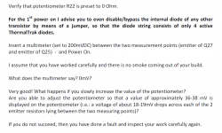
John, this problem should not happen with the transistors that I have matched for you!
I asked you to measure the voltage drop across each of the 6 TT-diodes on a PCB and disable the one that has the highest drop!
Did you do this?
Rudi
I asked you to measure the voltage drop across each of the 6 TT-diodes on a PCB and disable the one that has the highest drop!
Did you do this?
Rudi
Rudi You have not asked me to do anything ,this is my first post after building ,However i will do as you ask when i work out how to do it john
Rudi i am in the Guinness book of records for reading the builders manual However understanding all tech stuff i am not,,, page 34 i think i get it john
I have disabled each thermaltrak in turn I cannot get 5 to work they all act the same,so I fix in a bat42 as per the manual and it works ,its stable I am happy 🙂.
However I have a question I cannot find in the manual what do I set the pot to,i have so far set it to 21mv but should it be 36/38mv thanks john
However I have a question I cannot find in the manual what do I set the pot to,i have so far set it to 21mv but should it be 36/38mv thanks john
- Status
- Not open for further replies.
- Home
- Amplifiers
- Solid State
- Roender's FC-100 prototype and builder's thread