Thanks for Mihai who designed the amp and helps us to build it , Rudi,Metal and the other people who contributed to this project.
zsaudio🙂
zsaudio🙂
Good work Rudi!
Anyway ... let's hope that others NJL power transistors didn't come with the wrong internal schottky diode.
Mihai, do you have a suggestion for a quick check on the transistors to determine which diodes are used in them? I assume it's voltage drop, so what voltage should we look for?
Mihai, do you have a suggestion for a quick check on the transistors to determine which diodes are used in them? I assume it's voltage drop, so what voltage should we look for?
Its starting to make sense to do a big group buy from a single batch of known good and distributing them to the builders in this group buy.
Testing
"Then i drive the amp into clipping with about 1kHz sinus. The heatsink is still at 37C."
Hi ZSAUDIO, can you test at about half power and tell us the temp rise? Should be more then.
Loek
"Then i drive the amp into clipping with about 1kHz sinus. The heatsink is still at 37C."
Hi ZSAUDIO, can you test at about half power and tell us the temp rise? Should be more then.
Loek
This is a heatsink test, not an amplifier test.can you test at about half power and tell us the temp rise?
This amount of continuous dissipation is unlikely to occur in any music reproduction.
Code:
This is a heatsink test, not an amplifier test.Anyway i did the test. Here's my result.
I switched the amp on. I was waiting untill the temp stabilizes this time 38C (higher room temperature).
Then i was feeding the amp with an 1kHz sinus signal to get 25Wrms into 6R only resistive load. I was running the test for 60 minutes. I've got 40C measured near to one of the power BJT's.
zsaudio😉
Code:This is a heatsink test, not an amplifier test.
zsaudio😉
This is what i ment Andrew.
Thanks zsaudio for the measurement.Loek
While I am waiting for some missing components, I have been thinking about the alternatives that I will be going to offer you
in the forthcoming group-buy.
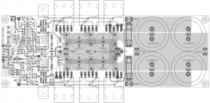
Here are the "rough" layouts of the 2 alternatives:
Alternative 1:

http://www.abload.de/img/fc-100_2_rev1usuqc.png
This alternative is following very closely Mihai's original design with 4 reservoir caps on the PCB.
The size of the PCB is 212 x 74 mm.
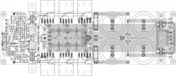
Alternative 2:

http://www.abload.de/img/fc-100_3_rev1tguae.png
This alternative contains the rectifier section additionally on-board.
The size of the PCB is 240 x 74 mm.
I did not change anything regarding the front- and backend on either layout.
Front- and backend have been sucessfully prototyped by ZSAUDIO and me, and this version is playing absolutely marvellous music
since several days on my test equipment.
I am only talking about the layout's PSU components.
Alternative 2 is following the "DX PSU" which has been published on Greg Erskine's homepage (see also attached image): Greg's Web Site
The PSU of Alternative 2 includes C-R-C filter, bleeder, status LED, ...

http://www.abload.de/img/fc-100_3_sch_rev1ehum2.png
I would appreciate very much, if the majority of you (who are interested to build this AMP) will decide and vote for Alternative 2,
because this is my preferred solution.
But I will of course honour your decision.
Best regards - Rudi_Ratlos
in the forthcoming group-buy.
Here are the "rough" layouts of the 2 alternatives:
Alternative 1:

http://www.abload.de/img/fc-100_2_rev1usuqc.png
This alternative is following very closely Mihai's original design with 4 reservoir caps on the PCB.
The size of the PCB is 212 x 74 mm.
Alternative 2:

http://www.abload.de/img/fc-100_3_rev1tguae.png
This alternative contains the rectifier section additionally on-board.
The size of the PCB is 240 x 74 mm.
I did not change anything regarding the front- and backend on either layout.
Front- and backend have been sucessfully prototyped by ZSAUDIO and me, and this version is playing absolutely marvellous music
since several days on my test equipment.
I am only talking about the layout's PSU components.
Alternative 2 is following the "DX PSU" which has been published on Greg Erskine's homepage (see also attached image): Greg's Web Site
The PSU of Alternative 2 includes C-R-C filter, bleeder, status LED, ...

http://www.abload.de/img/fc-100_3_sch_rev1ehum2.png
I would appreciate very much, if the majority of you (who are interested to build this AMP) will decide and vote for Alternative 2,
because this is my preferred solution.
But I will of course honour your decision.
Best regards - Rudi_Ratlos
Attachments
Last edited:
Hi Rudi,
it's nice to see you again on the board.
Good conceptions from you as always. I think if we use external rectifiers we can keep one pair of big elcos onboard conception. If we use onboard rectifiers we can go for 2 pairs version IMHO. Another way as i do it using double secondaries and double rectifier connecting the ground after the rectifiers and not at the trafo. Some people say it's an overkill but this is diy.

zsaudio😉
it's nice to see you again on the board.
Good conceptions from you as always. I think if we use external rectifiers we can keep one pair of big elcos onboard conception. If we use onboard rectifiers we can go for 2 pairs version IMHO. Another way as i do it using double secondaries and double rectifier connecting the ground after the rectifiers and not at the trafo. Some people say it's an overkill but this is diy.
zsaudio😉
Hi Rudi,
nice work. I'm flexible and happy with either version. Can you compare the sound with your other amps?
nice work. I'm flexible and happy with either version. Can you compare the sound with your other amps?
Hi Rudi,
Is there any chance to offer amplifier board without reservoir capacitors (please check posts #: 65, 72, 94 and 110).
With all-in-one approach interested diy's are forced to use certain type and size for the reservoir capacitors. What about people that prefer to use (or already have) "computer grade" capacitors and different rectifier?! Just because they like the amplifier they have to pay extra for something they will cutout.
Single board has a price/size like two just-amp boards.
How much will the shipment cost be for the all-in-one PCB? Probably close to double price, compared to just-amp boards.
Amplifier board is most critical regarding layout and have to be as close as possible to the proven original Roender's design. We need to give a people freedom to implement their own ideas and creativity. This way, as a result, we'll be able to see a lot of different amplifier layouts built around your excellent amplifier board.
To be fair toward all interested people, it would be really nice if you offer just-amp option together with other two options. I would not be surprised if most of the people order shorter and cheaper just-amp boards.
Best regards,🙂
Bob03
Hi Bob,
I will answer your "trivial" questions first.
The shipment cost is the same for any PCB-size as long as the size remains within DIN A4 (297 x 210mm) format
and the letter weighs less than 500 gr.
The cost is 3.45€ for worldwide shipment.
The cost of an AMP-only - PCB (Frontend and Backend without any reservoir CAPs and rectifier-section - the size is: 145 x 74 mm)
is 1.50€ less than the AMP-incl. PSU - PCB.
What many DIYers do not know:
If I would offer 2 PCB versions (one with, the other without PSU) I would have to transmit 2 different EAGLE layout files
to the etching company and pay the tooling costs twice!
Tooling costs consist of generating the GERBER files and exposing the Gerber files!
The tooling costs account for about 60€ per layout!
From an economic point of view it is much more profitable to order only "the big version".
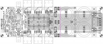
To make the PCB as versatile as possible I will insert additional connectors on the PCB and ask the etching company
to insert a pre-determined breaking line (see the pink line on the attached image), so that the PCB can be easily cut
and can be used without the on-board PSU.
Best regards - Rudi_Ratlos
I will answer your "trivial" questions first.
The shipment cost is the same for any PCB-size as long as the size remains within DIN A4 (297 x 210mm) format
and the letter weighs less than 500 gr.
The cost is 3.45€ for worldwide shipment.
The cost of an AMP-only - PCB (Frontend and Backend without any reservoir CAPs and rectifier-section - the size is: 145 x 74 mm)
is 1.50€ less than the AMP-incl. PSU - PCB.
What many DIYers do not know:
If I would offer 2 PCB versions (one with, the other without PSU) I would have to transmit 2 different EAGLE layout files
to the etching company and pay the tooling costs twice!
Tooling costs consist of generating the GERBER files and exposing the Gerber files!
The tooling costs account for about 60€ per layout!
From an economic point of view it is much more profitable to order only "the big version".
To make the PCB as versatile as possible I will insert additional connectors on the PCB and ask the etching company
to insert a pre-determined breaking line (see the pink line on the attached image), so that the PCB can be easily cut
and can be used without the on-board PSU.
Best regards - Rudi_Ratlos
Attachments
Last edited:
And some mounting points (screw holes) on both sides of the line please...To make the PCB as versatile as possible I will insert additional connectors on the PCB and ask the etching company
to insert a pre-determined breaking line (see the pink line on the attached image), so that the PCB can be easily cut
and can be used without the on-board PSU.
Include all 6 NJL diodes in the compensation string.
It is very easy to add a copper shorting wire across any individual diode.
As I posted earlier, it is also possible to drill oversize at any diode location and to bring the diode leads right through for other monitoring purposes.
One can also add a Schottky or resistor in parallel across any individual diode or even group of diodes.
Starting from all 6 in series allows maximum flexibility in experimentation. Then others can simply follow the recommendations after the experiments have been completed.
FranzM,
I will use the holes in the fuse-holder's case as mounting points.
And I will insert through-hole PADs above every diode.
(I have already done this for diode 3 and 6).
Thank you for your remarks.
Best regards - Rudi_Ratlos
I will use the holes in the fuse-holder's case as mounting points.
And I will insert through-hole PADs above every diode.
(I have already done this for diode 3 and 6).
Thank you for your remarks.
Best regards - Rudi_Ratlos
Good idea. The voltage across the fuses is low; in case of fuse blowing it will be no risc of arcing caused by these screws.I will use the holes in the fuse-holder's case as mounting points.
I have done the final "layout-cosmetics" last night and will now ask Cal Weldon (Moderator) to move this entire thread into
an AMP's forum thread entitled: "Roender's FC-100 prototype and builder's thread".
I will then open a new thread called: "Roender's FC-100 Rev.1 group-buy", where we can concentrate on the group-buy itself,
components of the "small kit" (if any), ...
Best regards - Rudi_Ratlos
an AMP's forum thread entitled: "Roender's FC-100 prototype and builder's thread".
I will then open a new thread called: "Roender's FC-100 Rev.1 group-buy", where we can concentrate on the group-buy itself,
components of the "small kit" (if any), ...
Best regards - Rudi_Ratlos
Last edited:
Rudi,
As you know I've the previous version is this OK to build if yes can you provide me all the information I need by mail?
Maybe I will purshase the second version too.
As you know I've the previous version is this OK to build if yes can you provide me all the information I need by mail?
Maybe I will purshase the second version too.
- Status
- Not open for further replies.
- Home
- Amplifiers
- Solid State
- Roender's FC-100 prototype and builder's thread