Some measurements.
When i switch on the amp i measure ~20mV on 0,1R Re. But it's hard to measure because it changes quickly.
After 5 minutes 19mV.
When the temperature of the heatsink stay constant (37C) i get 18,20mV-18,23mV
Then i drive the amp into clipping with about 1kHz sinus. The heatsink is still at 37C.

After several minutes i rise the frequency up to 10kHz temp is the same.

Later freq up to 50kHz fuses are blowing.

Swaping the fuses for bigger ones i continue the stress test. My heatsink warms up to 50C in several minutes but i have to stop because my dummy load (6R) is getting hot too hot.
I switch off the drive signal and measure the Ibias. I get 18,40 mV as soon as i remove the drive. Not so bad 0,20mV difference between normal condition and the condition after the stress test.
After the heatsink cools down to normal temperature (37C) i get back my original Ibias 18,20mV.
Comming back later with more measurements.....
zsaudio🙂
When i switch on the amp i measure ~20mV on 0,1R Re. But it's hard to measure because it changes quickly.
After 5 minutes 19mV.
When the temperature of the heatsink stay constant (37C) i get 18,20mV-18,23mV
Then i drive the amp into clipping with about 1kHz sinus. The heatsink is still at 37C.
After several minutes i rise the frequency up to 10kHz temp is the same.
Later freq up to 50kHz fuses are blowing.
Swaping the fuses for bigger ones i continue the stress test. My heatsink warms up to 50C in several minutes but i have to stop because my dummy load (6R) is getting hot too hot.
I switch off the drive signal and measure the Ibias. I get 18,40 mV as soon as i remove the drive. Not so bad 0,20mV difference between normal condition and the condition after the stress test.
After the heatsink cools down to normal temperature (37C) i get back my original Ibias 18,20mV.
Comming back later with more measurements.....
zsaudio🙂
Attachments
@ zsaudio: What transistors did you use? Type, brand, vendor? Can you monitor the unused thermal-trak diode as Rudi did?
according to Mihai's schematic:
q17, q13, q11 BC560C Onsemi. Vendor is Farnell.
q9, q7, q6 BC550C Onsemi. Vendor is Farnell.
J1-J2 2SK170BL Idss 9,31-9,31 mA. Vendor is a diyAudio forum friend.
2SC3423Y-2SA1360Y Toshiba from Ampslab.
For Q3-Q1 i use 2SA1837-2SC4793. Vendor is Mouser
Big Power BJT's are NJL0281D/NJL0302D Onsemi from Mouser.
Re resistors are 0,1R/3W VISHAY DALE - LVR03 1%.
More measurement later.
Regards,
zsaudio
🙂
All measurements were done without input lowpass filter(no C18) and without output coil.
The Zoble is installed onto the PCB.
100kHz sinus only pure resistive load.

100kHz sinus 2u2 capacitor added to the load.

As you can see the output amplitude decreased.
zsaudio
The Zoble is installed onto the PCB.
100kHz sinus only pure resistive load.
100kHz sinus 2u2 capacitor added to the load.
As you can see the output amplitude decreased.
zsaudio


Sorry for the bad signal qualities but my signal sours is a diy signal generator the osci is a Tektronix TDS2022B 200MHz 8bit.
zsaudio
zsaudio
input lowpass and output coil (10 turns on 12mm diameter + 10R resistor parallel) are installed.

The previous ringing damped somehow but still ringing.
The previous ringing damped somehow but still ringing.
input lowpass and output coil (10 turns on 12mm diameter + 10R resistor parallel) are installed.
View attachment 270811
The previous ringing damped somehow but still ringing.
It's very hard to pass the 0.1uF load test without some ringing. Did you saw any amplifier immune to this test? 🙄
It's very hard to pass the 0.1uF load test without some ringing. Did you saw any amplifier immune to this test?
Frankly speaking all of my amps shows the same behaviour and never took care about it but some people use this test for stability. I usually drive the amp with about 100kHz sinus and load resistive and capacitive 2n2-1u and look for oscillation. Doing this test i've not observed any funny things up to 200MHz what is the BW limit of my scope.
But i do not know. I can test the amp within my limitations. So if anyone has some request about test i try to do it.
Best Regards,
zsaudio🙂
PS, Mihai i really like your amp. I'll do some thd test tomorrow then will start to hook up the other channel. Just can't wait for listen to it.
Best Regards,
zsaudio
Best Regards,
zsaudio
Remove the output coil but let the input LP filter in place.
How fast is it (slew rate)?
I'm glad you like it from measuring POV but you'll like it more singing 😉
How fast is it (slew rate)?
I'm glad you like it from measuring POV but you'll like it more singing 😉
Hi Mihai,
output coil is removed now and input lowpass soldered (100pF).

http://www.diyaudio.com/forums/solid-state/51370-soundstage-class-ab-amps-2.html#post1394667
post 20 by Aksa interesting. I'll give it a try.
Best Regards,
zsaudio🙂
output coil is removed now and input lowpass soldered (100pF).
http://www.diyaudio.com/forums/solid-state/51370-soundstage-class-ab-amps-2.html#post1394667
post 20 by Aksa interesting. I'll give it a try.
Best Regards,
zsaudio🙂


ZSAUDIO,
thank you for all your measurements and efforts to prove the performance and stability of this AMP /PCB. Great job!
I will now start and correct the slight flaws of the layout that I found during my build of the prototype:
- emitter resistor PADs being very small
- clearance / isolation ring in the middle of the PCB being very small
- increase the space around C18
- rename all the components' names to confirm to Mihai's convention
- increase the space between emitter resistors and the 4 caps in the middle of the PCB
- reconsider the functionality of the embedded PSU
If you found additional issues during your prototype-build: please tell me (per EMail).
I will now connect the AMP to a "better-quality- source" (CDP), but have to build an attenuator (I will finish and use
my lightspeed passive attenuator) first.
If Mihai's FC-100 keeps being so promising, I will open a group-buy for it in April.
I am looking forward to your listening impressions.
Best regards - Rudi_Ratlos
P.S. And - of course - I will write a "FC-100 Builder's Manual".
Last edited:
I measured the THD1. I used my diyed 1kHz ultralow THD oscillator from Linear Tech LT1115 datasheet.
My spectrumanalyzer is an EMU 0404 USB a laptop win7 x64 software is Spectraplus 5.
Sorry for the 50Hz and sideband trashes but i did not take the time to tame them.
All measurements were done for 6R resistive load.
100mW

1W

10W

30W

My spectrumanalyzer is an EMU 0404 USB a laptop win7 x64 software is Spectraplus 5.
Sorry for the 50Hz and sideband trashes but i did not take the time to tame them.
All measurements were done for 6R resistive load.
100mW
1W
10W
30W
50W

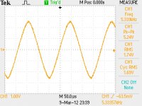
Before clipping

and the sinus signal on the scope.

Sorry guys for the mess signals but i thinks it's enough to show the amp's THD1 performance.
I'd measure THD20 if i could but i do not have the right equipment.
I know THD20 would be more interesting.
The amp (only one channel) plays music on an average speaker.
So the judgement will be on my better speakers when the other channel will be finished.
zsaudio🙂
Before clipping
and the sinus signal on the scope.
Sorry guys for the mess signals but i thinks it's enough to show the amp's THD1 performance.
I'd measure THD20 if i could but i do not have the right equipment.
I know THD20 would be more interesting.
The amp (only one channel) plays music on an average speaker.
So the judgement will be on my better speakers when the other channel will be finished.
zsaudio🙂
- Status
- Not open for further replies.
- Home
- Amplifiers
- Solid State
- Roender's FC-100 prototype and builder's thread