You may ask me:
"What is this all about? Why do you test and solder and report and ...?"
The answer:
In case I will ever offer this PCB for this beautiful AMP in a group-buy, I want to make sure that:
1) the layout is 100% perfect
2) everybody gets this AMP running, no matter, if he has 100% matched output transistors or not
This is the reason why.
Best regards - Rudi
@FranzM,
with a 3K9 or 2K7: the initial value of the voltage drop across the emitter resistors (with Vr = 0 Ohm) keeps being about 40mV.
When I "bypass" the whole 5-diode string with a 1K5, the initial value is 0 Ohm and I can easily adjust the value to 18 - 21 mV.
Bes regards - Rudi
with a 3K9 or 2K7: the initial value of the voltage drop across the emitter resistors (with Vr = 0 Ohm) keeps being about 40mV.
When I "bypass" the whole 5-diode string with a 1K5, the initial value is 0 Ohm and I can easily adjust the value to 18 - 21 mV.
Bes regards - Rudi
Bypassing a single diode with 510r is going too far.
If the diode Vf~400mV then 510r will bypass ~0.8mA.
That leaves just 1.5mA passing through the diode.
1k5 across all 5 diodes is going too far. That leaves just 0.6mA passing through the diodes.
Use 1k to 1k5 across each diode.
The Vre will drop as each extra resistor is added in parallel to it's diode.
The optimum Vre for 0r22 is not 18mV to 19mV.
It will likely be around 22mV to 23mV.
If the bypass resistors get the Vre down to about or just below optimum then you have proved that for your setup that 2.3mA through the diode string is too high.
Do that first.
Then seek out a final solution.
Please notice post #102: http://www.diyaudio.com/forums/soli...compensation-thermal-trak-transistors-11.html
A shot in the dark because currents were checked, but did you select your green diodes according to the BOM?:
D2, D3, D8: Green LED type LT433B or any other rectangular LED with Vf>=1.9V at If=5mA
D2, D3, D8: Green LED type LT433B or any other rectangular LED with Vf>=1.9V at If=5mA
Believe it or not:
This AMP can play music.
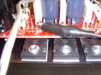
I am being a little bit tired of soldering resistors in parallel, diodes in series, ..., I just bypassed the 5th diode,
connected a 5€ - speaker and switched power on.
And yes: the music sounds very well.
Maybe I will go on soldering and bypassing and testing and ... tomorrow.
Best regards - Rudi
P.S. @POOGE: Yes, I did.
This AMP can play music.
I am being a little bit tired of soldering resistors in parallel, diodes in series, ..., I just bypassed the 5th diode,
connected a 5€ - speaker and switched power on.
And yes: the music sounds very well.
Maybe I will go on soldering and bypassing and testing and ... tomorrow.
Best regards - Rudi
P.S. @POOGE: Yes, I did.
Attachments

Franz,
the date-code, when my NJL0281s have been produced, is CO0932.
The date-code, when my NJL0302s have been produced, is CQ1042.
I will ask OnSemi nevertheless.
Best regards - Rudi
P.S. It would be a great pity, if I cannot give the "GO" for this PCB.
It is indeed sounding very good (even with 4 diodes only) - Michael Jackson playing.
Attachments
Last edited:
Andrew,
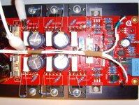
I did, what you asked me for and soldered a 1K resistor across each of the diodes.
With a trimm-resistor's value of 0 Ohm the inital voltage drop across an emitter-resistor is now 35 mV (instead of 45 mV without the additional resistors).
Best regards - Rudi_Ratlos
I did, what you asked me for and soldered a 1K resistor across each of the diodes.
With a trimm-resistor's value of 0 Ohm the inital voltage drop across an emitter-resistor is now 35 mV (instead of 45 mV without the additional resistors).
Best regards - Rudi_Ratlos
Attachments
Andrew,
I did, what you asked me for and soldered a 1K resistor across each of the diodes.
With a trimm-resistor's value of 0 Ohm the inital voltage drop across an emitter-resistor is now 35 mV (instead of 45 mV without the additional resistors).
Best regards - Rudi_Ratlos
Guys,
Maybe ONsemy had changed the internal diode into 0302/0281 NJL series?
Maybe your transistors have other type of diode than mine!
BR,
Mihai
Mihai,
I measured the internal voltage drop of the NJL thermal track diodes with my DMM yesterday.
With power-off I measured the current that my DMM is inducing (0.9mA) and measured exactly 500mV dropping across each diode.
This corresponds to the datasheet.
Best regards - Rudi_Ratlos
I measured the internal voltage drop of the NJL thermal track diodes with my DMM yesterday.
With power-off I measured the current that my DMM is inducing (0.9mA) and measured exactly 500mV dropping across each diode.
This corresponds to the datasheet.
Best regards - Rudi_Ratlos
Mihai,
I measured the internal voltage drop of the NJL thermal track diodes with my DMM yesterday.
With power-off I measured the current that my DMM is inducing (0.9mA) and measured exactly 500mV dropping across each diode.
This corresponds to the datasheet.
Best regards - Rudi_Ratlos
The Vf has nothing in common with diode tempco (temperature coefficient). They are both function of If but not direct related
Last edited:
would they change the specs and not update the datasheet?
It is just a supposition ... I do not know if is true.
What happened with Rudi's amplifier is very strange because he didn't change anything in RMI-FC100 design.
Rudi,
What is the voltage dropped over BE junctions of Q19 (2sc4323) and Q20 (2sa1360)?
Also, please verify with a DMM that all the base stopper resistors are the right values (2r2 for power transistors and 10ohm of CFP drivers)
BR,
Mihai
What is the voltage dropped over BE junctions of Q19 (2sc4323) and Q20 (2sa1360)?
Also, please verify with a DMM that all the base stopper resistors are the right values (2r2 for power transistors and 10ohm of CFP drivers)
BR,
Mihai
Mihai,
the base stoppers are definitely 2R2 and are 10 Ohm for CFP drivers.
The voltages on the pre-drivers are:
2SC3423 - Emitter: 618 mV - Collector: 26.4V - Base: 1216mV
2SA1360 - Emitter: -607mV - Collector: -26.6V - Base: -1195mV
Best regards - Rudi
P.S. I have measured with only 4 active diodes and the trimm-resistor being adjusted to give an optimal voltage drop for
the emitter resistors.
Last edited:
Rudi,
The Vbe over power BJTs should be around 580mV, hence the total voltage dropped over all output stage BE junctions is around 2340mV + 2*18mV Vre = 2376mV.
My diodes has 470mV when they are at the working temperature, so 5*470 = 2350mV, which is very close with the above calculation.
Q: What Vf did you find for your NJL diodes when the amplifier is at the working temperature?
Cheers,
Mihai
In post #288 I wrote that after "by-passing" each of the 5 diodes with a 1K resistor the voltage that drops across an emitter resistor
decreased by 10 mV to 35 mV (instead of 45 mV without the additional resistors) with the trimm-potentiometer' value being 0 Ohm.
AndrewT. suggested to decrease the bias current from 2.3mA (that I currently have) to 1.8mA - 2mA.
Which is the best way to do this?
Best regards - Rudi
decreased by 10 mV to 35 mV (instead of 45 mV without the additional resistors) with the trimm-potentiometer' value being 0 Ohm.
AndrewT. suggested to decrease the bias current from 2.3mA (that I currently have) to 1.8mA - 2mA.
Which is the best way to do this?
Best regards - Rudi
In post #288 I wrote that after "by-passing" each of the 5 diodes with a 1K resistor the voltage that drops across an emitter resistor
decreased by 10 mV to 35 mV (instead of 45 mV without the additional resistors) with the trimm-potentiometer' value being 0 Ohm.
AndrewT. suggested to decrease the bias current from 2.3mA (that I currently have) to 1.8mA - 2mA.
Which is the best way to do this?
Best regards - Rudi
The best way is to have all five diodes inserted into the thermal compensation circuit. We need to have the total diode string TC equal with the total output stage Vbe TC (at the If = 2.2mA). There is no work around here.
But, if the ONsemi had changed the diode inside the NJE then the above doesn't apply anymore because the TC of the diode had changed from the original value of -1.6mV/grd C.
Last edited:
Mihai,
I have measured the diode's VF on "the fly".
The AMP is running since half an hour.
The voltage that drops across any diode is 500mV.
Best regards - Rudi
P.S. I do not have connected the AMP to a speaker (load) right now.
I will do this now, let him play for some time and measure the diodes again.
I have measured the diode's VF on "the fly".
The AMP is running since half an hour.
The voltage that drops across any diode is 500mV.
Best regards - Rudi
P.S. I do not have connected the AMP to a speaker (load) right now.
I will do this now, let him play for some time and measure the diodes again.
Last edited:
- Status
- Not open for further replies.
- Home
- Amplifiers
- Solid State
- Roender's FC-100 prototype and builder's thread