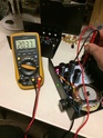
Without op Amp.. Measure the voltage from the 3 pinout in middle of pcb after input make sure right polarity and turn till both same.
I'm sure Richard mention it somewhere.. I read through the whole thread always before proceed with project
Thanks Anthony, you mean use the V+, REF and REF, V- using the DMM and get the voltage right on the both the sides right?
Correct.. There is 3 pcb point v+ v- reg after the supply.. Solder out wires
so can attach 2 set dmm(crappy 3 bucks one even) and measure so plus to center and center to minus is same using the trimpot. Best to recheck after 10 mins again then proceed to other board.
It will be above or under 12v its fine.
Also.. Grounding..power wiring. Look through in phonoclone thread. It's clearly explained. Or is it the manual I forgot
Last edited:
I am getting +/-12VDC from the off board bridge rectifiers which are connected to +/-12VAC dual secondaries transformer. So using these 3 PCB points should I change the incoming +/-12VDC to +/-18VDC which is what will be powering the Opamps? When you say set the voltage after the V++,Com, V-- using the trimmer to what voltage do I need to set on the pcb points?
Thanks
Thanks
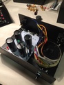
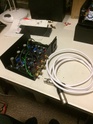
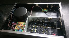
A couple of pics of my Emerald. I cut a Naim case in half and welded a strip to each half of the sled. Each half was just big enough to get the boards in. I've lost the pics of the finished units so i'll have to post them later.

Very nice..pretty build!
It's mentioned somewhere.. No caps in the transformer box I tried both with and without.. Richard is right. 1000 uf in the main board is all needed for best sound
Also... I moved from talema toroid to Japanese r core. It's a huge leap in performance.
Quiet, weight and clarity mainly is the difference
Ok I used the trimmer to get the same positive and negative voltages to +/-11.44VDC on the pcb points. I am unable to get this to 12v as either the negative or the positive voltages change with reducing or increasing the trimmer.
Thanks
Thanks
Ok I used the trimmer to get the same positive and negative voltages to +/-11.44VDC on the pcb points. I am unable to get this to 12v as either the negative or the positive voltages change with reducing or increasing the trimmer.
First, thank you to AnthonyA for running the support dept. for me earlier. Sorry I'm late...
+/- 11.5 V is about what the regs will end up at when centered with the trimmer. It's explained in the Build Manual / BOM file that you download from my web site. Last worksheet, marked "notes".
The trimmer just centers the COM between V+ and V-, it doesn't change the total voltage from V+ to V-.
You measure 12 VDC at the rectifier output because you haven't connected the boards yet. When you do, they'll measure 18 V.
/R
I'm well aware of Richard's preference regarding the power supply but I've always built two box kit with some dc filtering in the psu enclosure. Old habits die hard though I'm always open minded. However as this phono stage is with a good friend and unlikely to return for some time I may be forced to build another if I'm to find out.

Ok I powered up and the first mono board I was able to get to +/-11.45vdc using the trimmer after like 10mins or so. Now on the second board testing I could get it to +/-11.85vdc using the trimmer. This difference of voltage is fine between the boards? Please note that when I tested this I did one board at a time.
thanks
thanks
ground loop issue
Hi all,
a while back I built my emerald preamp with great success, but I have noticed excessive woofer movement to my loudspeakers due to wrapped records or tonearm - cartridge matching, even though according to my tonearm's mass and cartridge compliance I should be at the 9-11 Hz range..
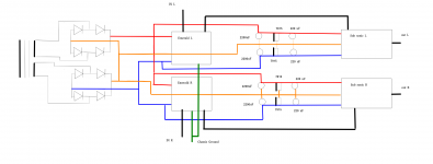
Anyways, I built two sub sonic filter circuits (one for each channel) which require +/- 15 V DC which I am getting from a regulated power supply connected to the bridge rectifiers that supply the emerald pcbs (see diagram).
Thick red lines represent V+, thick blue lines show V- and thick orange lines are the common 0V. Thick black lines are shielded cables for the signal, and green lines are the ground wires that attach to the chassis where the tonearm's ground wire connects to the chassis.
The problem is that I am now getting nasty hum which is caused most likely by some ground loop.
Any thoughts on what did I do wrong?
Hi all,
a while back I built my emerald preamp with great success, but I have noticed excessive woofer movement to my loudspeakers due to wrapped records or tonearm - cartridge matching, even though according to my tonearm's mass and cartridge compliance I should be at the 9-11 Hz range..
Anyways, I built two sub sonic filter circuits (one for each channel) which require +/- 15 V DC which I am getting from a regulated power supply connected to the bridge rectifiers that supply the emerald pcbs (see diagram).
Thick red lines represent V+, thick blue lines show V- and thick orange lines are the common 0V. Thick black lines are shielded cables for the signal, and green lines are the ground wires that attach to the chassis where the tonearm's ground wire connects to the chassis.
The problem is that I am now getting nasty hum which is caused most likely by some ground loop.
Any thoughts on what did I do wrong?
Attachments
The problem is that I am now getting nasty hum which is caused most likely by some ground loop.
Any thoughts on what did I do wrong?
I don't think you did anything wrong. It's just that these things tend to happen when you try to power two independent audio circuits (four, actually, if stereo) from a single power transformer.
Simplest solution is to install a small power transformer and rectifier bridge for the filter circuit, so you don't run them off the Emerald supply. The filter circuit shouldn't be critical to the sound quality: no need to be picky on parts.
The Emerald has no rumble filter, none of my phono stage designs do. True rumble is about 1 Hz, and should be attenuated by the output coupling cap, but cartridge resonance 5-10 Hz wont be, since the 3dB of the output RC filter is going to end up about 4-5 Hz typically. One simple thing you can try if you don't want to use the separate filter circuit is to just use a small capacitor for C3. The value depends on the impedance of the following stage, but say 0.47 uF or even 0.33 uF would still get you 98% of your bass response while attenuating the infrasonic by 10-20 dB.
Hi Richard,
thank you for your reply. I will buy a new transformer with four separate secondary windings (2x12 and 2x15) to isolate the circuits. It is true that one should avoid running many power supplies or bridge rectifiers from the same secondary winding. Regarding the coupling capacitor I would prefer to use the sub sonic filters as they provide 36db/octave attenuation with a corner frequency of 18Hz and will be more effective in reducing the rumble. For the record I am using Rod Elliot's design.
Ha, I was wondering if it was the E.S.P. circuit. Anyhow, separate secondaries should clear up the problem.
Ha, I was wondering if it was the E.S.P. circuit. Anyhow, separate secondaries should clear up the problem.
more progress, more questions...
I got a new (used) transformer with three secondary windings
0-12V which I am using as a separate aux power supply
20-0-20 which is being used for the ESP filter
18-0-18 (yes, it is center taped 😡) which I am using with one full bridge rectifier and I am getting 27-0-27V rectified and filtered (if there's a capacitor across each rail to ground).
Before I changed over my old transformer, which has two 0-12V secondaries, I inserted a 1.5 ohm resistor (measures 1.8 ohm) in series with V++ and measured 86mV on it which is equal to approximately 50mA (two channels driven). So far so good. The S-reg project page states that the circuit is able to work with a load that draws up to 60mA, so I assume everything checks ok so far.
As you can see my new transformer has a considerably higher secondary which has to drop a bit. There are several ways to achieve this.
So far I tried a voltage divider on the secondary using 22ohm and 44ohm resistors which allow for 13-0-13v across the 44ohm resistors and draw 270mA in total but the resistors are getting very hot for my liking.
Second attempt I inserted 300 ohm resistors in series to the V++ and V-- and I was getting +/-12.5 at the V+/V- reference points which seemed to be ok but I was measuring 12.8V at the V++/V--. So that can't be right. I assume I was limiting the current too much.
The last thing I thought was to build a voltage divider using a 33-47ohm resistor and a 18V zener diode. That would allow a voltage drop of 9V at the resistor with approximately 200mA flowing through it.
Any thoughts what would be the best option. Most likely it is something I haven't thought yet.
There are two option, if you insist on staying with a 36 V secondary.
First, and what I'd recommend, is just regulate the V++ and V-- down to 18 VDC before bringing the power to the Emerald. With a LM7818/7918 or whatever circuit you are comfortable with. Dropping resistors are bad idea.
Second would be to rebuild the Emerald for use with 27 V V++/V--. The voltage rating on the filter caps would have to be raised to 35V, and several resistor values would be changed, but it is doable.
There are two option, if you insist on staying with a 36 V secondary.
First, and what I'd recommend, is just regulate the V++ and V-- down to 18 VDC before bringing the power to the Emerald. With a LM7818/7918 or whatever circuit you are comfortable with. Dropping resistors are bad idea.
Second would be to rebuild the Emerald for use with 27 V V++/V--. The voltage rating on the filter caps would have to be raised to 35V, and several resistor values would be changed, but it is doable.
Hi Richard,
I thought about the regulated +/- 18v too.
My filter caps are rated at 35V and I have some leftover resistors. Is it possible to give instructions how to rebuild the emerald boards to work with 27V please? This sounds interesting..
Keep the original transformer for phono stage duties and use the new one for auxiliary supply and ESP filter. Leave the 18-0-18 winding disconnected. You can stack the toroids if space is tight.
Keep the original transformer for phono stage duties and use the new one for auxiliary supply and ESP filter. Leave the 18-0-18 winding disconnected. You can stack the toroids if space is tight.
This will work, but I'd rater use a single transformer...I am sure it can be done..
- Home
- Source & Line
- Analogue Source
- RJM Audio Emerald Phono Stage Help Desk