Ok, hold off. It may be a day or so until I can get around to it.
sure, no problem.. your help is much appreciated..
It might be a nice addition to your spreadsheets too. You may want to include a function to calculate some resistor values with respect to the input voltage. Similar to the gain calculations you already provide. It may be handy for other users too..
 just a thought..
Im sure this has come up before but are the resistors in parallel or in series with the load jumper OPEN and the switchboard in use? The 100 ohm resistor I mean. I am trying to arrive at between 1000 and 2000 ohms for example.
TIA
TIA
@WntrMute2
Parallel. The 47k of the Emerald is always part of the input load, the components of the Switchboard add across it, each component in parallel. For 1k and 2k it doesn't play a significant role. The standard BOM Switchboard doesn't have a setting between 1k and 47k. Use 100, 221, 1000, and 2210 for example for R4,3,2,1.
@mimikos
I looked at the S-Reg design and it holds up nicely to higher voltage. That is, it is a pretty good regulation circuit. The problem is that as you increase the voltage Q3 and Q4 will dissipate more power, and there isn't anything you can do to change that really. So just use 35V caps for C4,5 and maybe put a small heatsink on Q3 Q4 and you should be good to go.
Hi all,
a while back I built my emerald preamp with great success, but I have noticed excessive woofer movement to my loudspeakers due to wrapped records or tonearm - cartridge matching, even though according to my tonearm's mass and cartridge compliance I should be at the 9-11 Hz range..
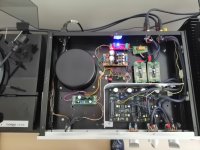
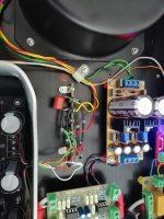
Anyways, I built two sub sonic filter circuits (one for each channel) which require +/- 15 V DC which I am getting from a regulated power supply connected to the bridge rectifiers that supply the emerald pcbs (see diagram).
Thick red lines represent V+, thick blue lines show V- and thick orange lines are the common 0V. Thick black lines are shielded cables for the signal, and green lines are the ground wires that attach to the chassis where the tonearm's ground wire connects to the chassis.
The problem is that I am now getting nasty hum which is caused most likely by some ground loop.
Any thoughts on what did I do wrong?
Even I am getting the excessive cone movement when I play some tracks on my TT via Emerald. I presumed that this was normal movement with my Shure M44-7 cartridge. So what exactly does this subsonic filter does?
Thanks
@WntrMute2
Parallel. The 47k of the Emerald is always part of the input load, the components of the Switchboard add across it, each component in parallel. For 1k and 2k it doesn't play a significant role. The standard BOM Switchboard doesn't have a setting between 1k and 47k. Use 100, 221, 1000, and 2210 for example for R4,3,2,1.
@mimikos
I looked at the S-Reg design and it holds up nicely to higher voltage. That is, it is a pretty good regulation circuit. The problem is that as you increase the voltage Q3 and Q4 will dissipate more power, and there isn't anything you can do to change that really. So just use 35V caps for C4,5 and maybe put a small heatsink on Q3 Q4 and you should be good to go.
Thanks Richard.. I will try this out!
Even I am getting the excessive cone movement when I play some tracks on my TT via Emerald. I presumed that this was normal movement with my Shure M44-7 cartridge. So what exactly does this subsonic filter does?
Thanks
This is a high pass filter with a very steep slope (36db/octave in my case but you can configure it at 18db/octave too) and a corner frequency (-3db) around 20 Hz which is the bottom end of the human hearing. The response from 20 Hz upwards is flat, the phase on the other hand is affected as you would expect from a filter. I think it's 180 degrees.
Even I am getting the excessive cone movement when I play some tracks on my TT via Emerald. I presumed that this was normal movement with my Shure M44-7 cartridge. So what exactly does this subsonic filter does?
Thanks
Depending on the frequency, simply reducing the value of the output coupling capacitor C3 may solve your problem, if indeed it can be called a problem. There is always going to be a certain amount of low frequency vibration when playing LDs. The question is whether it can be considered excessive.
Hi,
Just got all my parts together after having the boards for a while.
Bare with me but I'm confused about the JP1 switch. I plan to use it for MM
Do I insert the jumper 1,2?
what about 3,4?
Second question, resistors, use the Bom for the 8.2R or the schematic 6.8R?
Thank-you
Looking forward to the build
Cheers!
Kirk
Depending on the frequency, simply reducing the value of the output coupling capacitor C3 may solve your problem, if indeed it can be called a problem. There is always going to be a certain amount of low frequency vibration when playing LDs. The question is whether it can be considered excessive.
Thanks Richard, my current C3 value is 2.2uF and I have some Russian PIO 1uF caps which I think I will try and see if it makes a difference.
@fiftyfivefilms
For MM, leave both jumpers open. For MC, both jumpers closed. For the normal build there is no case where you'd have one open one closed situation.]
For part two, err, the emerald has neither 8.2 nor 6.8 ohm resistors, so I’m going to have to guess that you mean the 68 ohm resistor R3, which is shown as 82.5 ohms on the schematic. Answer: it doesn't matter. 68 ohms gives about 59 dB of MC gain, 82 ohms about 57 dB. The BOM has a worksheet where you can put in the resistor values and it will spit out the gain and load that results.
/R
Thanks for the speedy reply...Yes my mistake on the resistor values typing to quickly...
so I don't need the jumpers at all I'll leave them off the board!
Cheers!
so I don't need the jumpers at all I'll leave them off the board!
Cheers!
@mimikos
I looked at the S-Reg design and it holds up nicely to higher voltage. That is, it is a pretty good regulation circuit. The problem is that as you increase the voltage Q3 and Q4 will dissipate more power, and there isn't anything you can do to change that really. So just use 35V caps for C4,5 and maybe put a small heatsink on Q3 Q4 and you should be good to go.[/QUOTE]
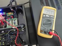
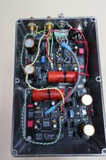
Success!! The S-reg is solid as a rock providing +/-12.5V from a +/-26V DC source.
Q3 and Q4 are barely warm to the touch after I played a whole lp, so no heatsinks needed for the time being at least.
No excessive woofer cone movement or hum any more with the use of separate transformer secondary windings.
I looked at the S-Reg design and it holds up nicely to higher voltage. That is, it is a pretty good regulation circuit. The problem is that as you increase the voltage Q3 and Q4 will dissipate more power, and there isn't anything you can do to change that really. So just use 35V caps for C4,5 and maybe put a small heatsink on Q3 Q4 and you should be good to go.[/QUOTE]
Success!! The S-reg is solid as a rock providing +/-12.5V from a +/-26V DC source.
Q3 and Q4 are barely warm to the touch after I played a whole lp, so no heatsinks needed for the time being at least.
No excessive woofer cone movement or hum any more with the use of separate transformer secondary windings.
Attachments

@fiftyfivefilms
R2 (100 ohms) and R3 (~68 ohms) can also be omitted if you are building it as a straight MM stage.
@mimikos
That's great news! I also see you've implemented front panel switches for gain and loading. Very nice.
R2 (100 ohms) and R3 (~68 ohms) can also be omitted if you are building it as a straight MM stage.
@mimikos
That's great news! I also see you've implemented front panel switches for gain and loading. Very nice.
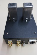
Just finished my Emerald, standard build and BOM, but I thought I include some photos of a slight variation; I used some cool giant 2.0uF Vitamin Q's mounted on top, bypassed with some Jupiter 0.22uF wax caps underneath. I also added a switch for MM/MC. so far so good!
Cheers
Cheers
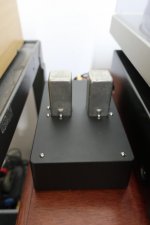
What size enclosures / what enclosure are people using??
I think I want to mount it as per Peter's original design with PSU and Phono stage seperate but can't seem to find any details about recommended enclosures
I think I want to mount it as per Peter's original design with PSU and Phono stage seperate but can't seem to find any details about recommended enclosures
@fiftyfivefilms That's some big capacitors! At first I thought you had some transformers mounted on the top there!
@saukoa The boards are each 8x10cm. As you can see from the photos, some people use chassis not much bigger than what can hold the two boards. The Hammondmfg 1590D series cases are popular. However, unless you know you are comfortable working with such tight spaces (say, its already your second build) I strongly recommend a substantially larger enclosure like the 1590F, or at least the new midsize 1590DE.
@saukoa The boards are each 8x10cm. As you can see from the photos, some people use chassis not much bigger than what can hold the two boards. The Hammondmfg 1590D series cases are popular. However, unless you know you are comfortable working with such tight spaces (say, its already your second build) I strongly recommend a substantially larger enclosure like the 1590F, or at least the new midsize 1590DE.
- Home
- Source & Line
- Analogue Source
- RJM Audio Emerald Phono Stage Help Desk