Dear Richard,
The two board are working now with this mesurement:
Board 1:
Tp1: 33,02V
Tp2: 9,59V
Tp3: 9,31V
Board 2:
Tp1: 33,02V
Tp2: 9,47V
Tp3: 8,95V
The music is little bit close, not very dynamic, but I think because they need a burning time.
The big problem are hum, hiss an some random oscillation.
I have opened the preamp box and keep the power line really far from input and output line without any audible result.
Please, can you point my attention where I can look at to solve these problems?
Thank you in advance.
Inviato dal mio ALE-L21 utilizzando Tapatalk
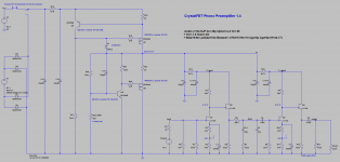
note: part no. for rev 1.3c boards
The random oscillation is a new one. Not sure what is going on there.
The voltages you gave earlier seem perfect, so there is no obvious problems.
Please measure the voltage across R17 and R24 and let me know the result. (They are 22 ohms?)
One thing to try is adjust trim R20 to V+ / TP1 = 31 V instead of 33 V.
Also, after that, try increasing or adding more capacitance to C15.
Finally, disconnect V++ from one board and just use one channel to see if the hum is the same or better.
Richard
The big problem are hum, hiss an some random oscillation.
The random oscillation is a new one. Not sure what is going on there.
The voltages you gave earlier seem perfect, so there is no obvious problems.
Please measure the voltage across R17 and R24 and let me know the result. (They are 22 ohms?)
One thing to try is adjust trim R20 to V+ / TP1 = 31 V instead of 33 V.
Also, after that, try increasing or adding more capacitance to C15.
Finally, disconnect V++ from one board and just use one channel to see if the hum is the same or better.
Richard
Dear Richard,
Your support is fantastic!
With your comment: "the voltage seem perfect" point me to check all my chain.
After some investigation I have found my Thorens td160 have a big problem with the ground.
Fixed it, 99% of the hum is gone and no more oscillations!
But the hiss remain too loud to listen to music at reasonable volume.
Now, r17 and r24 are 22 ohm, and voltage are:
Board 1
R17: 0,543v
R24: 0,287v
Board 2
R17: 0,545v
R24: 0,287v
But change r20 to have com-tp1 31v made my day: hiss now is audible only at 3/4 of the volume, may be the reason why is how I build the case.
Next try will be change the back connection on the preamp case.
I will keep you informed.
If you need other measurements, please let me know.
Thank you again.
Inviato dal mio ALE-L21 utilizzando Tapatalk
Now, r17 and r24 are 22 ohm, and voltage are:
Board 1
R17: 0,543v
R24: 0,287v
Board 2
R17: 0,545v
R24: 0,287v
These are also "perfect". No issue here.
But change r20 to have com-tp1 31v made my day: hiss now is audible only at 3/4 of the volume, may be the reason why is how I build the case.
With any phono stage, if you turn up the preamplifier volume high enough eventually you can expect to hear substantial hiss through the speakers. That's normal, but of course the volume level needed for music playback should be much lower than that.
I can't think of a reason why changing V+ from 33 V to 31 V should have drastically altered the output noise. Hum, yes. Noise, no.
If you can record the output noise of the CrystalFET (with no input attached) and send the file to me we can look at the noise spectrum together and see if the problem can be identified.
If you want I can send you my old pair of working boards so you can check whether the problem is your boards or your case connections.
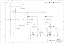
rev 14e final
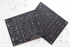
This is the last revision of the board for the forseeable future. The boards (black matte) are on order and I'll get them in a week or so.
This is the last revision of the board for the forseeable future. The boards (black matte) are on order and I'll get them in a week or so.
Attachments
Dear Richard,
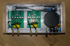
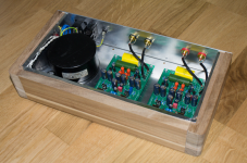
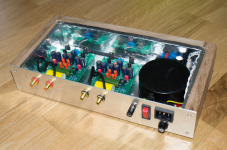
sorry for delay my answer but I was busy this week, anyway yesterday I have open he preamp case and I have try to understand if the noise i heard was made from the power line.
The good news is that your project is not so sensible to the power line, because to hear some 50Hz influence I have to have the power line really close to input line!
Enclose you will fine both channel audio file I have record with my mobile, I hope they are enough to verify if everything is right.
Again, thank you for all your support.
Attachments
(Note: I assume we are looking at the stereo recording from a smartphone, held close to the left or right speakers. Correct me if I am mistaken.)
While visually the two signals look quite different, the noise spectrum tells us the only real difference is a large 50 Hz component in the right channel.
The rest is a solid "comb" of power line harmonics up to 2 kHz, seen equally on both channels. Some of it can be correlated to the charging current, some of it looks more like the rectified voltage.
So the "hum" problem in the right channel needs to be addressed, this is a noise pickup/shielding/grounding issue, while the "buzz" noise in both channels is also higher than expected (I don't know the absolute level of course, but given that it is clearly visible above the broadband noise means it is certainly higher than what I have.). This could be caused by faulty circuit components or, more likely given your voltages are all correct, is noise pickup due to ground loop or poor shielding.
I should say that looking at what you've built I would not think there to be a problem with grounding/shielding... so yes, I'm a bit confused as to why this is happening, though it is possible the reverse voltage blew out the mosfets I can't imagine the regulator still functioning if that was the case.
Perhaps the best thing is for me to send you my extra set of completed boards?
Attachments


Last edited:
Another 1.2a (almost) finished
Hello
last weekend I managed to continue my build based on the 1.2a boards. First listening tests are very promising, full body, smooth highs. No audible hum (the mu-shielded transformer (originally Linn Pre) seems to do no harm although it is quite close to the board. No audible noise (still need to measure).
Configuration is currently still original BOM 1.2a, I crank'd up the CCS though to have some more margin (reminder: need to heatsink the TO220). I will modifiy the PSU according to RJMs last findings.
kind regards, Daniel
Attachments
Looks good.
It seems like you have some extra filtering off-board, so you can ignore my previous remarks re. increasing C15.
Out of curiosity,
- by how much did you crank up the CCS?
- how do the boards connect to the chassis GND?
- where did you get those red axial capacitors for C2-5? They look neat.
/R
It seems like you have some extra filtering off-board, so you can ignore my previous remarks re. increasing C15.
Out of curiosity,
- by how much did you crank up the CCS?
- how do the boards connect to the chassis GND?
- where did you get those red axial capacitors for C2-5? They look neat.
/R
Thanks 🙂Looks good.
- current is ~29mA (R17 = 24Ohms), All the rest currently BOM 1.2a, emitter resistors still active- by how much did you crank up the CCS?
- how do the boards connect to the chassis GND?
- where did you get those red axial capacitors for C2-5? They look neat.
/R
- currently signal ground is not connected to chassis ground. Don't have any hum. I'll test other configs though.
- Capacitors are Vishay K460 Series KP 63V 33n 1%. I bought them at a German distributor for quite a low price (they said 10% tolerance but they are 1% 🙂)
BTW: just measured an output noise voltage of ~160µV (DIN Audio 20-20k, 100 Ohm input resistor). This translates to -70dB re 0,5mV input referred (60dB gain, ignoring RIAA). I'll measure again after PSU mods.
kind regards, Daniel
Last edited:
Thanks for your reply.
The noise figure seems about what I would expect. The RIAA eq. complicates the relationship between broadband 20-20k noise and the FFT noise baseline : most of the contribution is <100 Hz due to the bass boost. That said, your build and mine appear to line up closely.
With a single box, earthed chassis, the connection between the board GND and chassis can be left out - and in rare cases this might be even preferable to avoid ground loops. This may be something other people might want to look at if they are having hum problems.
Last edited:
PSU Mods
Hello RJM and all,
i did the latest modifications to the PSU (PSU emittor resistors shorted) and remeasured the noise at the output. In my measurement setup (using National VP-9690A noise meter) a difference is bearely measurable, from 160µV now down to ~150µV (-0,5dB).
I left the current setting resistor R17 unchanged though, so CCS current went down to 25mA from 29mA. I'll change this and measure again.
This will be my last test though since I am very satisfied as it is and will concentrate on listening 😀
Thanks again for this nice phono stage!
kind regards, Daniel
PS: Black-n-white looks good ;-)
Thanks for the update. Sounds like you are "good to go".
Now all I need is to get jekocomputer sorted out and I can more-or-less sign off on the development stage of this project.
Now all I need is to get jekocomputer sorted out and I can more-or-less sign off on the development stage of this project.
I'm currently using the Elliot p06 phono which is pretty good for my MM ortofon. Using OPA2134.
Hi-Fi RIAA Phono Preamp
Of course I'm always up for a build if there's a chance of getting better sound!
Is latest version of CrystalFET still inferior in the bass performance when compared to a good op-amp phono?
Hi-Fi RIAA Phono Preamp
Of course I'm always up for a build if there's a chance of getting better sound!
Is latest version of CrystalFET still inferior in the bass performance when compared to a good op-amp phono?
There is no substantial difference between versions. I fixed some errors, added/removed some features, and removed a couple of unneeded parts.
Maybe some other people can chip in here. I don't find there is anything missing in the bass, but the smoothness is such that you are just more aware of, and interested in, the midrange.
Maybe some other people can chip in here. I don't find there is anything missing in the bass, but the smoothness is such that you are just more aware of, and interested in, the midrange.
Would be nice to see some additional feedback from users. I will be finishing my High Octane Phono and that would be an interesting comparison as well although I have not yet decided to purchase CrystalFET boards.
Dear Richard,
Now the preamp is working perfectly and I can say it is fabulous.
I have changed both the psu mosfets and transistors and now everything is fine.
Thank you for all your support.
Inviato dal mio ALE-L21 utilizzando Tapatalk
Now the preamp is working perfectly and I can say it is fabulous.
I have changed both the psu mosfets and transistors and now everything is fine.
Thank you for all your support.
Inviato dal mio ALE-L21 utilizzando Tapatalk
- Status
- Not open for further replies.
- Home
- Source & Line
- Analogue Source
- RJM Audio Crystal P jfet phono preamplifier | development thread