
CrystalFET development 17 Feb ~ April 7 2016
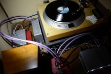
And just like that, it was playing music.
It sounds really good. Better than I was expecting. Clear and languid, with superb vocals. And of course dead quiet, just as the FFT showed it would be.
And just like that, it was playing music.
It sounds really good. Better than I was expecting. Clear and languid, with superb vocals. And of course dead quiet, just as the FFT showed it would be.
Attachments
Okay, let's take a stab at describing what it sounds like:
My reference is the phonoclone. The phonoclone makes my LPs sound pretty comparable to a digital track of the same recording. Low noise, good detail resolution and soundstage, and neutral response.
In direct comparison to the CrystalFET, however, the phonoclone sounds dry and a bit shouty. It's a very by-the-numbers canvas. Everything is there, accurately represented right to the corners, but overall it seems rather flat, with little sense of life or nuance. Very much like a CD, if you want to go there.
The CrystalFET projects. The music comes out at you. It engages your full attention, in fact the emotional connection it sets up is on a completely different level. This is going to come out kinda weird, but the best way I can describe it is as follows: you don't just hear the music anymore, you hear the intent of the musicians performing it.
So that's that, in one fell swoop CrystalFET is my new reference point for all things vinyl.
However, all is not perfect: at 50 dB, I'm short 5~8 dB of gain I really need. So I will be tweaking thing soon to try and get that. In other shortcomings I should mention, bass is perhaps not as solid or impactful as I might like, and it can start to sound a bit confused on large scale, complex passages. I suspect this is related to having all those RC filter stages in the power supply and/or the electrolytic bypass caps of the source resistors.
That seems to have worked out well.
I'm back up to a workable 54 dB gain. No adverse effects that I can see.
The current decreases, the transconductance decreases, and the output impedance increases. Since both amplifiers are buffered by a follower stage however there are no dire consequences as a result of the decreased drive. I'm not sure what the practical limit is but 60 dB (~~1 mA I_ds) seems do-able (just?).
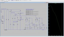
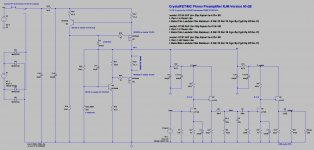
The attached schematic is my own version of the circuit, a collection of mods and with the paramaters of the jfets I actually picked out as the models.
I'm back up to a workable 54 dB gain. No adverse effects that I can see.
The current decreases, the transconductance decreases, and the output impedance increases. Since both amplifiers are buffered by a follower stage however there are no dire consequences as a result of the decreased drive. I'm not sure what the practical limit is but 60 dB (~~1 mA I_ds) seems do-able (just?).
The attached schematic is my own version of the circuit, a collection of mods and with the paramaters of the jfets I actually picked out as the models.
Attachments

I'm thinking I should do a pivot and pitch this circuit not as a MM stage, but as a MC stage.
The long and short of it is as follows:
For the MM version, the gain is defined by V_gs0 and what with the other corners I've painted myself into with this circuit that means the circuit gain hovers around 30 dB and there isn't much I can do about it*. That's not going to be enough for a lot of people.
In the MC version meanwhile, transconductance (i.e. current) can be traded off for gain more-or-less as desired. There are disadvantages to doing this, but there are also advantages, and overall considering the circuit topology I have chosen the overall picture looks much more advantageous. In terms of noise and matching the J113 seems up to the task.
*An MM stage could be designed using source resistors which are split into bypassed and unbypassed sections. It would mean a board re-spin but nothing else needs to change.
I have modded my own version now up to 60 dB. I'll do some more listening and measurements and come back to this soon.
Keep that thought in mind!
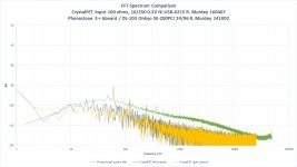
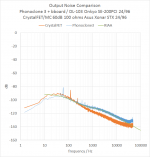
Here is a pretty close, apples to apples comparison between the output noise of my PC3 and CrystalFET stages. The gain should be very close, 60 dB in both cases.
The results are pretty close to what I predicted earlier. The CrystalFET blows past the OP27-based, active PC3 at higher frequencies, but has higher noise at lower frequencies. Trace power line harmonics are detected in both, hum in the case of the PC3 and residual ripple (as expected) in the CrystalFET.
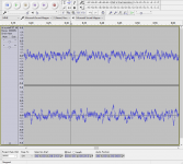
In my circuit, with R17=27.4 ohms, the supply draws 24 mA current through Q7, of which about half is shunted through Q7 and the rest used by the phono stage itself. The V+ is 34 V while the drain voltages (vs. GND) are 7.7~8.2 V and source voltages are 1.17~1.21 V. The V++ is 43 V with about 3 V p-p ripple.
Turn on and turn off output swing is less than 0.5 V.
That's really as far as I can reliably test it. The circuit appears to behave exactly as simulated, with no issues except for fractionally lower drain voltages.
Here is a pretty close, apples to apples comparison between the output noise of my PC3 and CrystalFET stages. The gain should be very close, 60 dB in both cases.
The results are pretty close to what I predicted earlier. The CrystalFET blows past the OP27-based, active PC3 at higher frequencies, but has higher noise at lower frequencies. Trace power line harmonics are detected in both, hum in the case of the PC3 and residual ripple (as expected) in the CrystalFET.
In my circuit, with R17=27.4 ohms, the supply draws 24 mA current through Q7, of which about half is shunted through Q7 and the rest used by the phono stage itself. The V+ is 34 V while the drain voltages (vs. GND) are 7.7~8.2 V and source voltages are 1.17~1.21 V. The V++ is 43 V with about 3 V p-p ripple.
Turn on and turn off output swing is less than 0.5 V.
That's really as far as I can reliably test it. The circuit appears to behave exactly as simulated, with no issues except for fractionally lower drain voltages.
Attachments
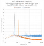
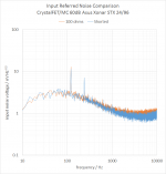
I took the data in the last post and calculated the input referred noise value. There is 1-2 dB error because I'm estimating the circuit gain.
The Phonoclone3 gives your datasheet OPA27 value of 4.5 nV/sqrtHz max, ~~3.5 in practical measure, plus little 60 Hz hum.
The CrystalFET gives you your datasheet J113 value, which is about 1 nV/sqrtHz at 10kHz and 6 nV/sqrtHz at 100 Hz, perhaps a fraction less in practical measure, plus a little 120 Hz ripple.
Both circuits are defined by voltage noise of the input stage active device. So we can conclude that the J113 jfet input stage provides about 10 dB lower noise than the OPA27 op amp in the midrange and treble bands.
Attachments
I took the data in the last post and calculated the input referred noise value. There is 1-2 dB error because I'm estimating the circuit gain.
The Phonoclone3 gives your datasheet OPA27 value of 4.5 nV/sqrtHz max, ~~3.5 in practical measure, plus little 60 Hz hum.
The CrystalFET gives you your datasheet J113 value, which is about 1 nV/sqrtHz at 10kHz and 6 nV/sqrtHz at 100 Hz, perhaps a fraction less in practical measure, plus a little 120 Hz ripple.
Both circuits are defined by voltage noise of the input stage active device. So we can conclude that the J113 jfet input stage provides about 10 dB lower noise than the OPA27 op amp in the midrange and treble bands.
100 Ohms, you must mean input shorted?
No, I mean inputs open with 100 ohms as the load resistor. This is close enough to having an actual cartridge plugged in so as be comparable to the phonoclone measurement, which must have a cartridge or dummy load on the input to develop the proper circuit gain.
No, I mean inputs open with 100 ohms as the load resistor. This is close enough to having an actual cartridge plugged in so as be comparable to the phonoclone measurement, which must have a cartridge or dummy load on the input to develop the proper circuit gain.
100 Ohms = ~1.28nv by itself? A MC cart with 100 Ohms ESR would be quite rare. DL103r is 14 Ohms IIRC.
Last edited:
My DL-103 is 40 ohms. I see your point, but it doesn't materially change the outcome except that the CrystalFET might be even better at high frequencies than the previous measurement suggests.
I'll re-do with inputs shorted to give a "best case" estimate of what the J113 is capable of.
I'll re-do with inputs shorted to give a "best case" estimate of what the J113 is capable of.
I realize I've jumped ahead in the last few posts, making several modifications to my CrystalFET that take it far away from the original BOM.
Since I only have a DL-103 I could never personally test out the MM version so I always planned to try and make a high gain version. To be honest I wasn't especially hopeful at the outset.
Fastforward and I have a 60 dB version up and running which has lower noise than my Phonoclone and sounds better as well. This I did not expect.
The attached LTSpice file is the circuit as I currently have my boards working at. The values are a combination of legacy versions, the parts I happened to have, and specific choices to match the jfets I used, so its a bit of a mess.
The simulation does, however, closely match the measured voltages and currents of my actual phono stage so if you want to go and poke around, you can take it as a reasonable approximation of what I have.
I will next try to walk things back to the beta kits and so forth changing the focus from the MM to the MC versions.
Attachments
My DL-103 is 40 ohms. I see your point, but it doesn't materially change the outcome except that the CrystalFET might be even better at high frequencies than the previous measurement suggests.
I'll re-do with inputs shorted to give a "best case" estimate of what the J113 is capable of.
Simply calibrating the gain by injecting a known 1mV signal at 1kHz would go a long way.
Here is the answer to your previous concern at least.
I'll think meanwhile about if a 1 mV source is feasible, or how best to go about it.
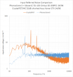
* the slight rise above 2-3 kHz is from the output noise intersecting with the measurement baseline of my soundcard, that's pretty much my limits.
I'll think meanwhile about if a 1 mV source is feasible, or how best to go about it.
* the slight rise above 2-3 kHz is from the output noise intersecting with the measurement baseline of my soundcard, that's pretty much my limits.
Attachments
Last edited:
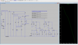
I should thank Scott for keeping me on the straight and level.
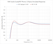
I measured the gain (soundcard output though my headphone amplifier, so as to drive the 100 ohm input accurately) and found it to be a lot lower than expected, at just 52 dB. I checked this a couple of different ways, I'm pretty sure it's accurate... though being so much lower than the simulation / calculation is worrisome.
The voltage noise replotted for 52 dB gain is shown below.
Attachments
- Status
- Not open for further replies.
- Home
- Source & Line
- Analogue Source
- RJM Audio Crystal P jfet phono preamplifier | development thread