Make a PDF of your PCB vendor list
It's difficult to read your breakdown of the PCB vendor list. Can you
create a larger PDF file so that we can read this document? Take care.
It's difficult to read your breakdown of the PCB vendor list. Can you
create a larger PDF file so that we can read this document? Take care.
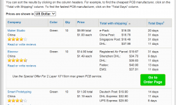
Try the steps outlined in post #2 above. Then hit CTRL + + + (control plus plus plus) in your internet web browser to make the image bigger, bigger, bigger. When I do this using Microsoft Internet Explorer, I get the image below. This image displays the first 3 in the list of 24 vendors; to see the others you would have to perform the steps in post #2, in your browser, and then use the scrollbar.It's difficult to read your breakdown of the PCB vendor list.
You can save the HTML to a file for later study, if you wish.
You can also open the attachment to post#20 above, and then click on the funny "X" in the lower left corner of the attachment. This zooms-out attached images to their original, full, size.
_
Attachments
scope plots using Chipamp P/S
Out of curiousity, I hooked up my scope up to the secondaries of a 750VA (Hammond 182U24) toroid with a Chipamp P/S, which does have MUR860 semiconductor fast diodes, but does not have any capacitor/resistor network ahead of the bridge. I didn't have the P/S heavily loaded. Maybe I need to pull a bigger load on it to see any ringing? At nominal volume load (i.e. playing music on 4 ohm speakers, but did turn it up pretty loud) the voltage curve was quite smooth, drilling down to 50 us and further...
Would a larger toroid tend to exhibit that high frequency ring less? And perhaps if it is going to happen, I would need to pull more amps to properly test for a ringing?
Just wondering.
Boba
Im my experience, high-VA toroids almost always have very low leakage inductance, hence very high ringing frequencies. Recall that f_ring is proportional to 1/sqrt(L_leakage). So I think you will need to set the scope for ~ 1 microsecond per horizontal division to see the oscillatory ringing.
There won't be much of it because the MUR series of ultrafast rectifiers is damn good at reducing dI/dt when the diode switches off. Although I haven't experimented with your exact MUR860 diode, I have measured its big brother, the MUR1520. Whereas your diodes are (Ultrafast, 8 amps, 600 volts), mine is (Ultrafast, 15 amps, 200 volts). Here is its datasheet. With the MUR1520 I see relatively low amplitude oscillation, about 10% of the secondary's 60Hz peak-to-peak amplitude. The ringing dies away in less than 7-8 cycles so you'll have to search for it carefully.
Summary: a good soft-recovery diode like the MUR860 drastically reduces osillatory ringing; adding a cheap CRC snubber to that, completely wipes out all ringing. Both in theory and in experimental practice.
Increasing the load current drawn from the supply will indeed increase the magnitude of the unsnubbed ringing; I see factors of 2 to 4 greater amplitude when I increase the load from 0.1 amp to 2.0 amps. It's not a gigantic effect but it does make a difference.
Edit- the figures attached to post #652 in the Quasimodo thread, may be somewhat helpful. Even though they're not an MUR diode and they're certainly not a high-VA toroid. (link)
Last edited:
Mark, let me thank you for the wonderful design. I have two questions. Could it possible to substitute FFPF30UP20STU for STTH3002 or STTH2002?
The second question relates to the capacitor Cx. As you said earlier
The second question relates to the capacitor Cx. As you said earlier
In this design you lowered Cx from 10nF to 3.3nF.A particularly handy set of parameters, which gives integer resistor values and integer damping factors, is (Cx=10nF, Cs=150nF, Ltrafo=1024uH).
In which cases it makes sense to reduce the value of the Cx? Is this in order to ensure compliance with Cs >= (200 * Cx) to explore zeta >= 10?Cranking through the Laplace mathematics, we find that one possible design of a universal snubber for 200VA, 2 x 22VAC secondary, toroidal transformers is:
(Cx and Rs should be exactly the values shown above; Cs can be 0.68 uF or any larger value. If you prefer to use Cs=1.0 uF, that will be just fine).
- Cx = 3.3 nF, metallized polyester film, stacked, rated 50VDC or higher
- Rs = 22 ohms, rated 1/4 watt or higher
- Cs >= 680 nF, metallized polyester film, stacked, rated 50VDC or higher
For "no-math snubbers" having zeta=1, this simplifies to (Cs >= (15 * Cx)) and indeed the Quasimodo starting recommendation is Cs=150nF and Cx=10nF ... a factor of exactly fifteen.
However, if for some inexplicable reason you wish to explore zeta >= 10, you won't get the overdamped non-oscillations you expect unless you set (Cs >= 150 * Cx). Depending on your own personal inventory of low dissipation factor (tan δ) film capacitors in your parts box, that might be {Cx=10nF, Cs=1.5uF} or, more likely, {Cx=2.2nF, Cs=330nF}.
Would the values of the snubber components have to be changed if I stayed with the Antek AS-2222 but changed the diodes or used a C-R-C-R-C combination after the diodes instead of the single pair of 22,000 uF caps?
In other words, do the values of the snubber components depend solely on the Antek AS-2222's parameters?
In other words, do the values of the snubber components depend solely on the Antek AS-2222's parameters?
Yes, it do ... assuming that Cx is much much greater than (Ctrafo + Crectifier).do the values of the snubber components depend solely on the Antek AS-2222's parameters?
Also you can use RC snubbers directly across the final output of the PSUused a C-R-C-R-C combination after the diodes instead of the single pair of 22,000 uF caps?
If you've put inductive, wirewound resistors on the board; or if you install explicit inductors to make CLC filters instead of CRC filters; these Output Snubbers may be beneficial.
If you use different diodes you'll need to check that their capacitance at zero volts of reverse bias, is far far smaller than Cx (3.3 nanofarads). The FFPF30UP20S diodes in the RingNot Bill Of Materials, are about 0.52 nanofarads according to Fairchild's datasheet: attached. Since 0.52 nF is far far less than 3.3 nF, this diode works fine with the (Cx,Cs,Rs) snubber values shown in the B.O.M.
If you plan to use the RingNot PCB layout, you'll need to buy diodes that fit the existing footprint on the board: TO-220 package, cathode on the left. Be sure to calculate the power dissipated in your new diode, and use that to calculate the junction temperature inside the diode. If you've chosen a high Vf diode like a HEXFRED it will get a lot hotter than the low Vf diode in the RingNot B.O.M. If you don't know how to calculate the power dissipation or the junction temperature of your new diode, don't make the substitution. Stick with parts choices that have been proven to work.
If you plan to use the RingNot PCB layout, you'll need to buy diodes that fit the existing footprint on the board: TO-220 package, cathode on the left. Be sure to calculate the power dissipated in your new diode, and use that to calculate the junction temperature inside the diode. If you've chosen a high Vf diode like a HEXFRED it will get a lot hotter than the low Vf diode in the RingNot B.O.M. If you don't know how to calculate the power dissipation or the junction temperature of your new diode, don't make the substitution. Stick with parts choices that have been proven to work.
Attachments

I plan to use the RingNot PCB layout as example so TO-220 package will not limit me. Also I will use a different transformer.
Quasimodo starting recommendation is Cs=150nF and Cx=10nF. But in this case you suggest Cs=680nF and Cx=3.3nF. As I see larger (Cs/Cx) ratio {200 instead of 15} provides large safety margin to choose Rs, isn't it?
Quasimodo starting recommendation is Cs=150nF and Cx=10nF. But in this case you suggest Cs=680nF and Cx=3.3nF. As I see larger (Cs/Cx) ratio {200 instead of 15} provides large safety margin to choose Rs, isn't it?
Maybe the best idea would be for you to start a brand new thread, and give it a title that reflects what you want to discuss.
- "Help me design a linear power supply? need to choose diodes, trafo, CRC filter components, snubber components"
Cheers for this Mark, I've just ordered a batch for a group of Uk friends. I'll pop some pennies in the diyaudio coffers.
Good luck & best wishes!
BTW I have a small number of fully assembled & tested RingNot boards for sale. Prices and info in post #1 above. When they sell out I'll edit post#1 to say so.
BTW I have a small number of fully assembled & tested RingNot boards for sale. Prices and info in post #1 above. When they sell out I'll edit post#1 to say so.
Good luck & best wishes!
BTW I have a small number of fully assembled & tested RingNot boards for sale. Prices and info in post #1 above. When they sell out I'll edit post#1 to say so.
very well your prices reflect what most of us can afford bravo!!
Will there be stuffed amplifier boards available??
Hello,
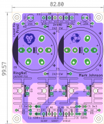
Here is a draft clone of ringnot PSU but with some options for components
1. snubber caps
2. Heatsink
3. Bulk Caps
I am also thinking if one could use a SK104 type heatsink with diodes attached on either side..
Mark, a question for you, How well would it work with default snubber components for those who dont have the set up?
150nF-150R-10nF? for a different transformer and may be slightly different voltages.
regards
Prasi
Attachments
Last edited:
Hi Prasi, very nice board! I request that you remove my name from the silkscreen since I will not be providing "technical support" for your board.
The optimum snubber component values depend upon the particular details of the transformer used. For the Antek AS-2222 and AN-2222 transformers, the values in the RingNot schematic (post #1) are acceptable. For a different transformer, you will need to either (a) measure the transformer secondary leakage inductance and then work through Jim Hagerman's equations; or else (b) connect it up to a bellringer test jig like Cheapomodo and find the optimum component values without doing any math calculations.
I also think people would be grateful if you would type out the exact part number of the heatsink your board design requires, made by Aavid and/or Wakefield and/or Ohmite and/or CTS.
Thanks for your comments Mark. I can only make options available to users in component choices on the PCB, its the end user who has to use components based on is better judgement and /or measurements.🙂
To others interested,
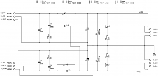
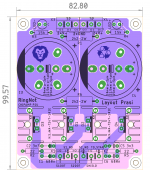
here are the gerbers which could be used on easyeda for 2USD + shipping for 10 PCBs. ALso attached is the schematic and stuffing guide.
There are many heatsinks that could be used on this layout, e.g. http://www.mouser.com/ds/2/303/w-sink-181565.pdf
or cheaper option 5 Pieces 25x23x16mm Radiator Cooling Fins TO 220 TO220 Extrusion Aluminum Heatsink-in Fans from Consumer Electronics on Aliexpress.com | Alibaba Group
here is another cheaper option but cant say about its
and many others.
similarly, the main bulk caps could be 10mm pitch-2 pin, 22.5mm pitch 4-pin or 25mm pitch-5pin.
All the best!
Regards
Prasi
To others interested,
here are the gerbers which could be used on easyeda for 2USD + shipping for 10 PCBs. ALso attached is the schematic and stuffing guide.
There are many heatsinks that could be used on this layout, e.g. http://www.mouser.com/ds/2/303/w-sink-181565.pdf
or cheaper option 5 Pieces 25x23x16mm Radiator Cooling Fins TO 220 TO220 Extrusion Aluminum Heatsink-in Fans from Consumer Electronics on Aliexpress.com | Alibaba Group
here is another cheaper option but cant say about its
and many others.
similarly, the main bulk caps could be 10mm pitch-2 pin, 22.5mm pitch 4-pin or 25mm pitch-5pin.
All the best!
Regards
Prasi
Attachments
Last edited:
too late to edit but the another ultra cheap option I was talking about is 20 Pieces/lot TO 220 TO220 Heat Sink 21x15x11mm Cooler Cooling Heatsink Radiator Aluminum-in Fans from Consumer Electronics on Aliexpress.com | Alibaba Group
but cant say about its thermal performance😀
but cant say about its thermal performance😀
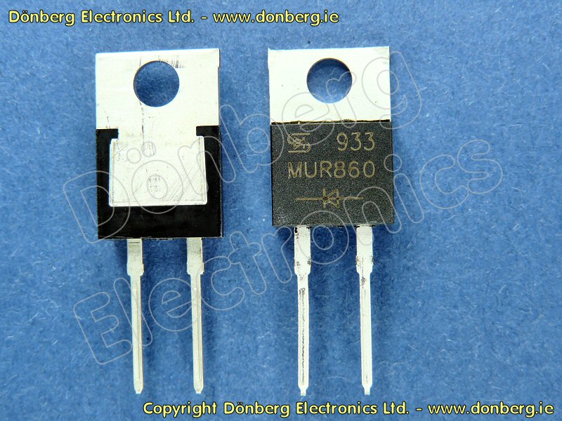
Hi, can I use MUR860 for this board. I plan to use it as psu for lm1875. Thanks 🙂 MUR860 uses TO220AC heatsink.
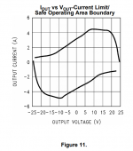
If it was me, if I wanted to drive a stereo pair of LM1875 chips with one RingNot PSU board, I would study Figure 11 of the LM1875 datasheet. It appears to me that a stereo pair of 2xLM1875 might, in the very worst case, draw (2 x 4.5 amps) from the positive supply, and (2 x 4.5 amps) from the negative supply. So I would be inclined to select diodes whose current ratings exceed the very worst case. Other designers might have a different opinion of course.
You'll need to compare the pinout of your diode against the pinout of RingNot's diode FFPF30UP20S. If they are identical, that's easier. If they are reversed, you'll need to rotate each of your diode+heatsink assemblies by 180 degrees before stuffing. Use a continuity tester, and slowly trace the board vs. the schematic to verify that you got everything correct. I wouldn't trim the diode leads or solder the heatsink mechanical support leg to the board, until AFTER verifying the hookup. Mistakes can happen!
And if your diode package has a metal tab (RingNot's FFPF30UP20S does not; it has an insulating plastic tab), you'll need to install a thermal insulator + heatsink grease between diode and heatsink.
_
Attachments

- Status
- Not open for further replies.
- Home
- Vendor's Bazaar
- RingNot: power supply for chip amps. Bare PCBs and/or assembled+tested units