Fast/soft recovery is nice.
What I do is put across the secondary, a small cap like 4.7nF, and a 100nF in series with a 1k pot. I connect the scope to the secondary through a highpass (like 100pF/10k) which removes the mains frequency, turn the pot until the ringing is damped, and replace it with a fixed resistor. Works very well and simple to do...
Scope shots (in that order) are : no snubber, pot too low, pot too high, just right.
Cool, nicee approach 🙂 How are those components wired ? all in series or the caps are in parallel and then the paralleled cap is connected in series with the VR ?
I use a slightly different method for connecting an RCA unbalanced output to a balanced input. I chop off one end of a RCA cable, and connect the core to pin 2 of the XLR and the screen to pin 3. Then I connect a 10 ohm resistor (optionally with a small capacitor in parallel) between pin 3 and pin 1.
The resistor is a compromise between breaking ground loops, draining RF from the cable screen, and allowing Class II ungrounded equipment to float, using up the common mode range.
The resistor is a compromise between breaking ground loops, draining RF from the cable screen, and allowing Class II ungrounded equipment to float, using up the common mode range.
Last edited:
I connect the scope to the secondary through a highpass (like 100pF/10k) which removes the mains frequency
That's a pretty good trick. I generally find that using the AC setting on the scope, triggering on the line voltage, while using the 10X magnifier to "zoom in" on the waveform gets me there as well. I'll try your HP filter.
At this point I'm just not seeing any ringing. I do see point where the diodes turn off, but no ringing.
I kept getting instability in the amplifier and everything he suggested did not work to cure it.
I looked in frustration at the sole capacitor "ringing frequency changer" and removed it.
The instability was gone.
Amplifier stability is a function of the loop gain and phase. If the amplifier's loop gain and phase change significantly when a 100 nF capacitor in the power supply is removed, I would argue that the amplifier has a serious design flaw.
The ringing of the transformer/rectifier was putting an interference signal into the amplifier and causing it to operate on the edge of instability.
Um, no... The amplifier was already operating at the edge of instability (crappy design) and the diode buzz may have pushed it over the edge and into instability.
Did you try putting the cap back in to see if the problem came back?
Those interested in snubber design will probably find CDE's app note on the topic useful.
~Tom
I use a slightly different method for connecting an RCA unbalanced output to a balanced input. I chop off one end of a RCA cable, and connect the core to pin 2 of the XLR and the screen to pin 3. Then I connect a 10 ohm resistor (optionally with a small capacitor in parallel) between pin 3 and pin 1.
The resistor is a compromise between breaking ground loops, draining RF from the cable screen, and allowing Class II ungrounded equipment to float, using up the common mode range.
You miss out on the CMRR that way, though. You'd be better off if you lobbed off the female end of an XLR cable and connected the XLR Pin 1 by your R||C network to the RCA shield. Then connect pin 2 to the center pin of the RCA and pin 3 to the shield of the RCA connector.
By using this approach, you're running pseudo-differential all the way from the source. With your approach, you're only running pseudo-differential from the input connector to the amp.
~Tom
As much as I have been enjoying these technical discussions (even learning some of it along the way) I am hoping to read more listening impressions from people who have completed their Modulus-86 amps.
As much as I have been enjoying these technical discussions (even learning some of it along the way) I am hoping to read more listening impressions from people who have completed their Modulus-86 amps.
I will definitely encourage all builders to post their reviews here, even if it's just a few lines. They're also welcome to send their reviews to me privately, if they prefer. However, I wouldn't blame my builders if they'd rather just kick back and enjoy the music... 🙂
Last note on the snubber: I see the ringing now. It helps if you connect the oscilloscope to the correct nodes in the circuit... 😱 There is some buzz when the rectifier diodes turn off. Adding 100 nF across the transformer windings reduces the frequency of the buzz to 67 kHz.
None - and I mean none - of the buzz is present on the output of the supply. Any issue (real or imaginary) arising from the presence of this buzz will be because the energy from the switching buzz is coupling into the rest of the amplifier. When the frequency of the buzz is in the 10s of MHz, it can often couple into sensitive circuits. In tight layouts, such as that of the Modulus-86, the coupling is minimal to start with. In circuits with bigger "antennae", such as point-to-point circuits or poor layouts, the coupling may be more of a concern.
Adding 100 nF across the transformer winding, thereby, reducing the frequency of the buzz below 100 kHz, reduces the coupling by orders of magnitude. 67 kHz is also well within the loop bandwidth of the Modulus-86, hence, any minuscule amount of buzz that may be coupled into the amp will be reduced by the loop gain. This is why that approach works.
As shown previously in this thread, it is possible to further dampen the switching transients by optimizing the snubber. However, this requires that each builder has the skill and equipment to perform the optimization. Each build would have to be optimized separately as the parasitic inductance and capacitance of the transformer, wiring, etc. vary from build to build.
The generic cap across the transformer winding is a good solution for those wanting to populate a board and be done, hence, this is what I recommend for my builders.
Coincidentally, I did happen to notice that HP/Agilent/Keysight (or whatever their nom d'jour) uses the cap across the secondary winding in the E3600A-series of power supplies.
~Tom
Last edited:
You miss out on the CMRR that way, though. You'd be better off if you lobbed off the female end of an XLR cable and connected the XLR Pin 1 by your R||C network to the RCA shield. Then connect pin 2 to the center pin of the RCA and pin 3 to the shield of the RCA connector.
What you just described is identical to what I do, except you are using a balanced cable and making the connection between cold and ground at the RCA end, whereas I use an unbalanced cable and make the connection at the XLR end.
I can't see how my method would hurt the CMRR of the balanced line receiver. I suppose the unbalanced cable will have worse CMRR than the balanced one, as the current that flows to ground through the resistor will drop a voltage in the cable screen.
I used to do it your way, but there is more room inside an XLR plug than a RCA for the grounding components, and I didn't notice any difference in the performance. Both ways seem effective at killing ground loop hum.
When a transformer secondary is connected to a CRC snubber, the only unknown is the transformer's secondary leakage inductance. All other design variables (rectifier choice, PCB layout, wiring harness construction, etc) are rendered irrelevant; they are swamped by the CRC.
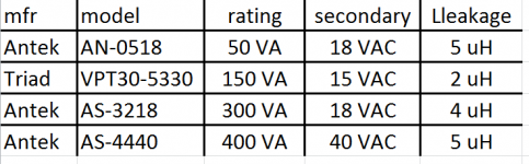
To find out more about this one and only unknown, I measured the secondary leakage inductance of four toroidal transformers that are approximately in the neighborhood of the Modulus recommended 200VA, 2 secondaries @ 22VAC each. Did it before lunch, today, using a pulse generator to resonate the secondary with a known capacitor. (Equation A-10 in the Quasimodo note, if you're curious).
I measured the leakage inductance of a single secondary winding, with all primary windings shorted and all other secondary windings shorted. All four transformers had leakage inductance between 2 and 5 microhenries; see table below.
But let's be extremely conservative. Let's suppose that some Modulus builders might possibly use transformers outside this range; let's suppose we want a single snubber that works for all secondary leakage inductances in the range 1uH < L < 100uH. This surrounds the actual measured data with quite a large margin-of-safety.
Fortunately, damping factor and snubber resistance are proportional to the square root of leakage inductance. So a 100-to-1 range of inductances gives only a 10-to-1 range of damping factor. I suggest choosing that range to be 0.4 < damping_factor < 4. At the low end, it's underdamped but not dreadfully so. At the high end, it's overdamped but not terrifying.
Cranking through the Laplace mathematics, we find that one possible design of a universal snubber for 200VA, 2 x 22VAC secondary, toroidal transformers is:
Try these out on your calculator or in SPICE simulation. You'll find that when leakage inductance is 1 uH, the damping factor is 0.4. When leakage inductance is 100 uH, the damping factor is 4.0. And when leakage inductance is 4 uH (which is the value actually measured on these four transformers), the damping factor is 0.8. Very comfortable.
Shoot, connect these up to your toroidal transformer and see how well they damp it (or fail to damp it). You can plug and unplug Rs or Cs to see both the with-snubber and without-snubber waveforms.
To find out more about this one and only unknown, I measured the secondary leakage inductance of four toroidal transformers that are approximately in the neighborhood of the Modulus recommended 200VA, 2 secondaries @ 22VAC each. Did it before lunch, today, using a pulse generator to resonate the secondary with a known capacitor. (Equation A-10 in the Quasimodo note, if you're curious).
I measured the leakage inductance of a single secondary winding, with all primary windings shorted and all other secondary windings shorted. All four transformers had leakage inductance between 2 and 5 microhenries; see table below.
But let's be extremely conservative. Let's suppose that some Modulus builders might possibly use transformers outside this range; let's suppose we want a single snubber that works for all secondary leakage inductances in the range 1uH < L < 100uH. This surrounds the actual measured data with quite a large margin-of-safety.
Fortunately, damping factor and snubber resistance are proportional to the square root of leakage inductance. So a 100-to-1 range of inductances gives only a 10-to-1 range of damping factor. I suggest choosing that range to be 0.4 < damping_factor < 4. At the low end, it's underdamped but not dreadfully so. At the high end, it's overdamped but not terrifying.
Cranking through the Laplace mathematics, we find that one possible design of a universal snubber for 200VA, 2 x 22VAC secondary, toroidal transformers is:
- Cx = 3.3 nF, metallized polyester film, stacked, rated 50VDC or higher
- Rs = 22 ohms, rated 1/4 watt or higher
- Cs >= 680 nF, metallized polyester film, stacked, rated 50VDC or higher
Try these out on your calculator or in SPICE simulation. You'll find that when leakage inductance is 1 uH, the damping factor is 0.4. When leakage inductance is 100 uH, the damping factor is 4.0. And when leakage inductance is 4 uH (which is the value actually measured on these four transformers), the damping factor is 0.8. Very comfortable.
Shoot, connect these up to your toroidal transformer and see how well they damp it (or fail to damp it). You can plug and unplug Rs or Cs to see both the with-snubber and without-snubber waveforms.
Attachments
I "discovered" this ringing issue for myself some time back, just through doing simulations of realistic power supplies and then worked out a snubbing strategy, again, purely from the Spice behaviour - only later did I discover it was a known issue, with that same, standard solution. At the time I applied it to everything I was playing with, including el cheapo audio components - and adding it caused a marked difference, improvement ... every time.
As long as the ringing stays in the secondary circuit and does not make it to the amplifier, is it really an issue? I think not.
In my circuit, I prevent the ringing from being coupled to the amp by reducing its frequency to the point where the coupling is
1) minimized
2) within the loop bandwidth of the amp, hence, suppressed by the loop gain
If it was an issue, I would expect to see a significant 60 or 120 Hz component in the noise floor measurements. As seen in the noise floor plot, there is no issue there.
Optimal snubber design is mostly relevant in switching supplies where the ringing at the turn-off of the switch causes excessive power dissipation in the switch and eats into the efficiency budget. For a linear supply the issue is coupling of the RF energy into sensitive circuits. One way to address this issue is to reduce the frequency of the ringing such that it falls in the 20 kHz ~ 100 kHz range the way I did. This way, it stays in the transformer and is not an issue.
~Tom
In my circuit, I prevent the ringing from being coupled to the amp by reducing its frequency to the point where the coupling is
1) minimized
2) within the loop bandwidth of the amp, hence, suppressed by the loop gain
If it was an issue, I would expect to see a significant 60 or 120 Hz component in the noise floor measurements. As seen in the noise floor plot, there is no issue there.
An externally hosted image should be here but it was not working when we last tested it.
Optimal snubber design is mostly relevant in switching supplies where the ringing at the turn-off of the switch causes excessive power dissipation in the switch and eats into the efficiency budget. For a linear supply the issue is coupling of the RF energy into sensitive circuits. One way to address this issue is to reduce the frequency of the ringing such that it falls in the 20 kHz ~ 100 kHz range the way I did. This way, it stays in the transformer and is not an issue.
~Tom
Thus your secondary leakage inductance is approximately 56 uH. The "universal" CRC snubber in post#408, gives a damping factor of 3 with this leakage inductance. When you finally do get rid of the temporary (Variac + 550VA xformer with wrong secondary), and replace it with the recommended Antek AS-2222, your measured leakage inductance will probably change.Adding 100 nF across the transformer windings reduces the frequency of the buzz to 67 kHz.
This is the exact reason why vacuum tube power amp guys are so enthusiastic about snubbers: they are greatly afraid that the diode-switch-off induced transformer ringing (which you call "buzz") will couple into the other transformer windings, and then from there, find its way to the various other B+ supplies in the amplifier. I guess vacuum tube amps typically have transformers with multiple secondaries. These folks are thrilled about a particular type of snubber which they call a "Reverse Recovery Spike Filter". Search the "bottlehead" forum of Audio Asylum and you'll find hundreds of enthusiastic DIYers saying that their vacuum tube amp sounds orders of magnitude better after they retrofitted an RRSF.None - and I mean none - of the buzz is present on the output of the supply. Any issue (real or imaginary) arising from the presence of this buzz will be because the energy from the switching buzz is coupling into the rest of the amplifier.
The straightforward capacitor plus resistor combo, of the right values, stops the ringing - simple as that. Why leave potential interference inside one's circuit, at some point, if it can be eliminated entirely? My philosophy is to get rid of, entirely, any sort of spurious signal generation ... and my ears thank me! 😉
Correct, it doesn't. The difference is far end ground sense allows the shield error term you mention to be reduced by receiver CMRR rather than passing through as a differential signal.I can't see how my method would hurt the CMRR of the balanced line receiver.
Should you check the SnR maths around the de facto pro audio convention of handling 100mV RMS ground offsets between devices you'll see why there's a market for balanced implementations approaching 100dB CMRR. 😉 DIY and home audio are normally significantly more friendly environments in this regard than festival gigs (uhh, who forgot to earth the generator again?) or cross mains circuit runs in old buildings with various generations of wiring (not uncommon in, say, concert halls). Normally isn't always; there are occasional posts from folks who encounter home situations where the 40dB CMRR of a basic balanced connection is insufficient.
Yup, main drawback of pseudodiff is the capacitances go out of balance some. Hence the movement of CMRR rolloff down a few kHz frequency you see in Tom's excellent measurements of post 384. Still beats the heck out of 0dB CMRR, which is pretty much the only other easy alternative to cracking open the source and installing a balanced send.The issue I see with balanced output is that you need to have both lines having the same source impedance curve, otherwise we are actually amplifying the difference.
They also tend to have a bunch of circuit nodes with impedances on the order of 100k to 1M and are forced into good size layouts due to valves being kinda big and component power handling requirements. So there's more noise susceptibility than in a sand amp where layout and component selection typically yields only a small area of impedances around 10k at the summing junctions of the control device. (If one's feeling paranoid it's another reason to use an integrated difference amplifier as well.)I guess vacuum tube amps typically have transformers with multiple secondaries.
Last edited:
When you finally do get rid of the temporary (Variac + 550VA xformer with wrong secondary), and replace it with the recommended Antek AS-2222, your measured leakage inductance will probably change.
I guarantee that it will change. It has to... However, unless it changes by orders of magnitude, the 100 nF cap will still ensure that the ringing doesn't couple into the rest of the circuit.
This is the exact reason why vacuum tube power amp guys are so enthusiastic about snubbers: they are greatly afraid that the diode-switch-off induced transformer ringing (which you call "buzz") will couple into the other transformer windings, and then from there, find its way to the various other B+ supplies in the amplifier.
That's probably true, however, completely irrelevant for the Modulus-86.
These folks are thrilled about a particular type of snubber which they call a "Reverse Recovery Spike Filter". Search the "bottlehead" forum of Audio Asylum and you'll find hundreds of enthusiastic DIYers saying that their vacuum tube amp sounds orders of magnitude better after they retrofitted an RRSF.
Have any of them posted the results of actual blind testing? The "tests" I have seen have all been sighted tests. In most, if not all, cases the has experimenter been sighted and often served dual roles both as a participant and experimenter. The confirmation that something works is basically confirmation bias. "I changed something so now it sounds better." I have a hard time taking these types of "studies" seriously.
Show me a before/after measurement which shows the impact of the change. If the issue is coupling between different B+ windings, it should be trivial to measure the "winding under test" with and without the snubber. Ideally, this would translate to a difference that could be picked up on the amplifier output as well.
Tube amps are a completely different animal. They have extremely poor (if any) supply rejection, hence, will be sensitive to any buzz on the B+ line. This is in rather stark contrast to the PSRR of any integrated amplifier circuit, including the Modulus-86.
~Tom
The straightforward capacitor plus resistor combo, of the right values, stops the ringing - simple as that. Why leave potential interference inside one's circuit, at some point, if it can be eliminated entirely?
Even with the optimized snubber, you'll still have a switching transient, so your interference source has not been completely eliminated.
Many of my builders don't own oscilloscopes, hence, don't have the tools to optimize the snubber. I'd rather provide something that works well for everyone than provide a solution that works well in only one specific configuration. Absolutely nothing prevents a builder from optimizing the default snubber.
I still maintain that if the diode switching transients are not detectable on the amplifier output and don't interfere with anything else, there is no issue. Millions of pieces of gear exist that don't have any snubbers at all -- including high-end gear.
~Tom
Last edited:
Why don't you increase your across-the-transformer capacitor to 2.0 microfarads, and thereby reduce the ringing frequency to 15 kHz? Your amplifier's open loop gain and PSRR are both higher at 15 kHz than at 67 kHz, so (it is hoped) the amplifier will provide even greater attenuation. And, as an added bonus, the ringing frequency will fall within the standard bandwidth of noise plots like the one attached to post#410. If there's no pimple at 15 kHz, good feelings abound. And if a single frequency THD test at 14 kHz shows no intermodulation with 15 kHz, more good feelings abound.
And there's the rub ... I would be quite certain that any conventional measuring will not detect what's going on - but the ears are certainly telling one that something has changed.Show me a before/after measurement which shows the impact of the change. If the issue is coupling between different B+ windings, it should be trivial to measure the "winding under test" with and without the snubber. Ideally, this would translate to a difference that could be picked up on the amplifier output as well.
The best strategy is to "train" one's hearing, using very specific recordings which highlight the variations, so that it becomes dead obvious where the alterations matter. This is something I have done for decades, and it's trivial to pick the less distorted configuration.
Just the capacitor gives third scope shot in my previous message, ie, it rings nicely and for a long time.
When something is ringing it means that energy is going back and forth between point A (usually a capacitor) and point B (usually an inductor). If you wait long enough this energy will be dissipated as heat. To get rid of the ringing, we need to dissipate this energy faster.
The only "active" part in a snubber is the resistor : it does the job of converting the unwanted energy into heat. No resistor means no snubber, just different ringing frequency. The capacitors are extras, their job is to ensure only the unwanted energy is dissipated, to reduce reduce waste heating.
Putting a resistor in parallel with a very low impedance has no effect, so the resistor has to be placed on the spot where dV/dt is highest. That is across the secondary. The other component that can dissipate unwanted energy is a ferrite bead, which you place on a spot where the impedance is low. However at the frequencies concerned by rectifier ringing, which are quite low, a resistor is more efficient.
Quasimodo is a nice bit of gear but IMO it is over-engineered, you can do the same with a 100pF capacitor and a resistor as highpass on your live circuit.
Last edited:
That's a pretty good trick. I generally find that using the AC setting on the scope, triggering on the line voltage, while using the 10X magnifier to "zoom in" on the waveform gets me there as well. I'll try your HP filter.
At this point I'm just not seeing any ringing. I do see point where the diodes turn off, but no ringing.
AC setting on scope will display a very large 50Hz waveform and a tiny rectifier glitch. So I use a highpass filter to look at the glitch with more detail. Opamps and the like usually have decreasing PSRR with frequency, so viewing the powersupply through a highpass filter actually kind of looks like how an opamp would react to it.
I think scopes should offer more bandwidth options... I often use various filters, lowpass, highpass etc, sometimes I want to observe a slow signal, but I don't want to turn off the energy saving lightbulb desk lamp...
Whilst we are sweating the last 2/10ths of a gnats fart does anyone have a view on steel bands (aka GOSS bands) on toroids. I'm not sure how, but this is a new one on me. The modulus-86 seems to be immune, but for an extra fiver seems that the psychological benefits would be worthwhile.
- Home
- Vendor's Bazaar
- Modulus-86: Composite amplifier achieving <0.0004 % THD+N.