More than 10dB better noise & THD. 🙂
If I take your circuit, throw bits out, change the values of some others and end up with more than 10dB better noise & THD, I think I'm entitled to say I understand it better than you. 😀
That's not what Patrick asked, his question was purely topological IMO. Changing bias levels is not a fundamental change.
Not 851/951 but other ZTXs. Some good ones I looked at in 1980 but you had to select for 1/f noise.Sorry, I'm not sure I follow what/how you did/mean. Are you saying ZTX851/951 are in production since 1980? Hmmm...
Back then, the Hitachi ones were superior all round. Today, I expect ZTX 851/951 to outperform the Hitachi & other Unobtainium supa devices in LoZ applications .. especially in common base
______________________
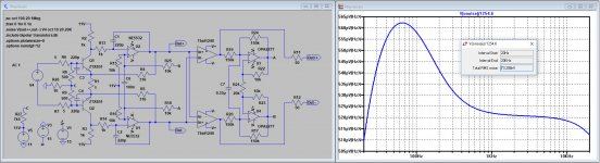
Thanks for these detailed investigation Syn. But non est tantum facile.Because we are at it, here's something you guys may find interesting. Since I decided to give it a shot when I'll get a chance to receive the ZTX devices, I thought it makes sense to evaluate the noise of a floating power supply..
... the internal resistance of the solar cell source is estimated to about 150ohm. ...
Bottom line, although feeding a MC Leach type preamp using one or more photocells seems straightforward, it still needs lots of attention with filtering, to avoid power supply noise injection.
The route between the floating PSU and the output isn't straightforward. You might like to put a little AC source in series with Han's sim of my circuit to find the effective 'CMR'. There are many subtleties in that circuit which I only found when trying to make something better. 🙂
I would be really grateful if you would post your results when you build your version of my circuit with a Solar cell. But the comparison should be with the Duraglit battery special which is the present reference. 😀
The PSU noise would certainly be a concern in JC's or anything with a grounded PSU.
Last edited:
I am suitably reprimanded Guru Wurcer .. but I did throw out some EVIL resistors ... as I did on JC's circuit 🙂That's not what Patrick asked, his question was purely topological IMO. Changing bias levels is not a fundamental change.
Da Brits have been at war with da French even longer than with da rebel colonials 😀I thought Brits only ignored work done in the US in this case it was done right across the channel.
Last edited:
For MC cartridges current noise does not matter much
Then neither does beta.
I would be really grateful if you would post your results when you build your version of my circuit with a Solar cell. But the comparison should be with the Duraglit battery special which is the present reference.
I all truth I don’t need to peek, last time I’ve checked I know how to bias two transistors together with all subtleties of the common base topology😀 And I’ll be if I know what a Duraglit battery special is, but I think I’ll survive without knowing.
IMO circuits have a fundamental performance limit, this is design. The component swapping and data sheet surfing is just play.
> If I take your circuit, throw bits out, change the values of some others and end up with more than 10dB better noise & THD,
> I think I'm entitled to say I understand it better than you.
The Leach circuit was not mine of course.
I guess I can claim the JFET version, but it is still the same topology.
And I have not seen simpler.
Cheers,
Patrick
> I think I'm entitled to say I understand it better than you.
The Leach circuit was not mine of course.
I guess I can claim the JFET version, but it is still the same topology.
And I have not seen simpler.
Cheers,
Patrick
I was talking about a real life comparison. There's stuff which in SPICE world can equal my Duraglit special but actually making one of them so it does isn't trivial. 😱I all truth I don’t need to peek, last time I’ve checked I know how to bias two transistors together with all subtleties of the common base topology😀 And I’ll be if I know what a Duraglit battery special is, but I think I’ll survive without knowing.
A big advantage of the Duraglit special is that it is easy to make and have SOTA noise performance. That's why I recommend making it up first and then spending a couple of years (maybe decades) trying to do better 😀
I can see a couple of bits to throw out & get better performance in your circuit ... but then it would be simpler than mine 🙂 Presently, they have the same component count if you don't count separate parallel capacitors.> If I take your circuit, throw bits out, change the values of some others and end up with more than 10dB better noise & THD,
> I think I'm entitled to say I understand it better than you.
The Leach circuit was not mine of course.
I guess I can claim the JFET version, but it is still the same topology.
And I have not seen simpler.
Last edited:
Thing is I can use up a tin of altoids quickly (and they are available here now days) but a can of duraglit takes me about 10 years, and my current silvo tin as a plastic screw top. Kiwi shoe polish tins would work but nowhere for the battery!There is no evidence the Altoids used by the rebel colonials anywhere near the performance of the Duraglit tins in Blighty and the loyal colonies!!
As a reference, my Duraglit battery special will be LOT easier to get to its theoretical/simmed performance. If you have the bits, you can knock it up in a morning and get SOTA performance immediately.
Actually getting into replace the battery seems the challenge with this approach. Both my tables have space under the tonearm for the unit but then gets a pain to change the power source. This is the trouble with very simple circuits, you end up angsting things that don't necessarily matter 🙂
I all truth I don’t need to peek, last time I’ve checked I know how to bias two transistors together with all subtleties of the common base topology😀 And I’ll be if I know what a Duraglit battery special is, but I think I’ll survive without knowing.
It's just Richards circuit in a metal tin! He has called it an 'altoids special' elsewhere.
Attachments

Originally Posted by Hans Polak 
Why do you keep asking ?
I have given a representative link twice.
The measurements were just a few pages back.
A Low Noise Balanced Input Moving Coil Preamp Using the ZTX851 - Page 39 - Pro Audio Design Forum
Here again the results of my sim
A Low Noise Balanced Input Moving Coil Preamp Using the ZTX851 - Page 44 - Pro Audio Design Forum
And below Wayne's exact circuit diagram, including the simmed noise results, -142.7dBV or -140.5dBu.
This is even 0.56dBu below -141.06dBu from Wayne measurements.
Hans
Why do you keep asking ?
I have given a representative link twice.
Because I may have missed the measurements results; all I see are simulations only.
The measurements were just a few pages back.
A Low Noise Balanced Input Moving Coil Preamp Using the ZTX851 - Page 39 - Pro Audio Design Forum
Here again the results of my sim
A Low Noise Balanced Input Moving Coil Preamp Using the ZTX851 - Page 44 - Pro Audio Design Forum
And below Wayne's exact circuit diagram, including the simmed noise results, -142.7dBV or -140.5dBu.
This is even 0.56dBu below -141.06dBu from Wayne measurements.
Hans
Attachments
Thanks for this Hans.
I shall now claim to have Lee'd JC in da 21st century as I Lee'd Leach in da 20th. 😀
It is likely I tried exactly this circuit in 1980 but I could be wrong or I found something in real life that put me off. The missing piece in the jigsaw is THD performance with level which I measured then.
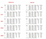
Hans, can you do THD on both circuits at 150uV, 50uV, 15uV & 5uV in addition to Bonsai's 500uV? Same 4R3 & currents please.
Then someone with exemplarery LN, PCB & build skills needs to
The difference between the 2 circuits in real life is the yucky stuff in da EVIL 1000uF caps is less obvious in my circuit. But the (hopefully) easier mains power in JC's makes it worth further investigating.
- make both my little battery circuit in a Duraglit tin
- JC's in a mains powered version
- compare them in a real life MC vinyl system
This is exactly what I expect.
The 4R3 and 3mA point is just below the point where increasing current doesn't improve Env. The difference becomes more marked at higher currents where real life will see Env levelling off .. eg as measured by H&H and Wayne.
Here it is:
Attachments
Originally Posted by Hans Polak
Why do you keep asking ?
I have given a representative link twice.
The measurements were just a few pages back.
A Low Noise Balanced Input Moving Coil Preamp Using the ZTX851 - Page 39 - Pro Audio Design Forum
Here again the results of my sim
A Low Noise Balanced Input Moving Coil Preamp Using the ZTX851 - Page 44 - Pro Audio Design Forum
And below Wayne's exact circuit diagram, including the simmed noise results, -142.7dBV or -140.5dBu.
This is even 0.56dBu below -141.06dBu from Wayne measurements.
Hans
So you are relying on other people measurements. Ok, I'm confused. Too many schematics, measurements and simulations. Somebody has to put these ducks in a row.
https://www.diyaudio.com/forums/ana...tra-low-noise-mc-head-amp-18.html#post5834677
As Scott already mentioned, something stinks in these simulations; the ZTX devices bias is not obvious, but the minimum noise of a bipolar transistor should be 1/gm thermal noise. For a device biased at 5mA, this is about 5ohm, or 2.5ohm for a pair, 3ohm if you add the emitter resistor.
You got 0.52nV/rtHz flat, subtracting the input 10ohm that is 6.2ohm equivalent left. Which leaves a noise of 3.2 ohm (or 6.4ohm per halve) equivalent unaccounted (since RB=0 in your model).
These things are way to slippery to be treated casually...
0.52nV/rtHz minus 10R is 6.2R, agreed, minus 1R/2 between the emitters is 5.7R.You got 0.52nV/rtHz flat, subtracting the input 10ohm that is 6.2ohm equivalent left. Which leaves a noise of 3.2 ohm (or 6.4ohm per halve) equivalent unaccounted (since RB=0 in your model).
These things are way to slippery to be treated casually...
To be divided between the two ZTX devices gives 2R85 per transistor, of which 2R25 to be accounted to Re with 5.5mA.
When changing Rb to 1R5 as suggested by Richard, noise becomes 0.57nV/rtHz flat, leaving 9R or 4R5 per transistor afters subtracting 10R + 1R/2.
The problem is though that measurement and simulation are drifting 0.8dB farther apart to 1.36dB in favour of the measurements !
So in fact when having to suspect Waynes figures, means that we have to take his measurements with a corn of salt, not a very elegant statement.
Hans
Last edited:
Does anyone have a guestimate for the common mode noise pickup on an MC cart? WK's circuit is elegant, but is a floating transducer with <10 ohm source resistance and say 2m of twisted and/or shielded cable going to suffer pickup that badly?
Genuine question - not seeking to prove a point either way, just curious.
Genuine question - not seeking to prove a point either way, just curious.
0.52nV/rtHz minus 10R is 6.2R, agreed, minus 1R/2 between the emitters is 5.7R.
To be divided between the two ZTX devices gives 2R85 per transistor, of which 2R25 to be accounted to Re with 5.5mA.
When changing Rb to 1R5 as suggested by Richard, noise becomes 0.57nV/rtHz flat, leaving 9R or 4R5 per transistor afters subtracting 10R + 1R/2.
The problem is though that measurement and simulation are drifting 0.8dB farther apart to 1.36dB in favour of the measurements !
So in fact when having to suspect Waynes figures, means that we have to take his measurements with a corn of salt, not a very elegant statement.
Hans
I am assuming that RB shown in the model is WRONG at 0.025 and should be 1.5 and for RE an error of similar magnitude.
I propose we change the model to reflect H&H AoE figures then.
Does anyone have a guestimate for the common mode noise pickup on an MC cart? WK's circuit is elegant, but is a floating transducer with <10 ohm source resistance and say 2m of twisted and/or shielded cable going to suffer pickup that badly?
Genuine question - not seeking to prove a point either way, just curious.
Like WK’s design, I’m using a differential amp for my floating 38R MC Cart, with 1.5 meter cable between them.
I can even touch the pins of the Cart with my bare hands, only resulting in an almost unhearable 50 Hz hum.
So instead of a badly suffering pickup, it must be seen as a substantial step forward with fenomenal Cmrr.
Hans
Does anyone have a guestimate for the common mode noise pickup on an MC cart? WK's circuit is elegant, but is a floating transducer with <10 ohm source resistance and say 2m of twisted and/or shielded cable going to suffer pickup that badly?
Genuine question - not seeking to prove a point either way, just curious.
To my experience, balanced phono designs are an useless luxury. There's nothing they can practically provide that a good shielded balanced to single ended signal cabling cannot solve.
- Home
- Source & Line
- Analogue Source
- Richard Lee's Ultra low Noise MC Head Amp