Albert Willemsen and Niko Bel - 1980 JSSC Vol. SC-15 No. 2
Thanks
You may contact Bill 🙂$$$ Ortofon
George
>Edit. I found this (for the strong players)
http://www2.elo.utfsm.cl/~lsb/elo102/ejercicios/GP_DOCU.pdf
8 in parallel @10mA each plus an 1ohm common source resistor takes you around 0.4nV/rtHz flat (measured) and 3-400Hz noise corner frequency, a smidge worse than the now extinct BF862 (around 0.35nV/rtHz)
Good point JFET's have to be measured the 2/3 gm rule is an approximation based on diffusion profiles, etc. My measurements agree the BF862 beats it by a couple of percent and most others actually measured about 10% worse (which I didn't factor in).
How is the Lee circuit different from the Leach ?
Because no negative feedback is used, the circuits cannot oscillate
From the horse's mouth no less. 😀
I'm not fussed about current flowing in the coils. The wont burn out and it wont 'dampen' anything . Plus I wanted to be contrary 🙂
That´s only until you´ve spent your hard earned money to buy a Jan Allearts cartridge, and burnt it 😀😀😀
That´s only until you´ve spent your hard earned money to buy a Jan Allearts cartridge, and burnt it 😀😀😀
Just curious, has anyone ever heard of a burnt MC Cart at switch on ??
Hans
Just curious, has anyone ever heard of a burnt MC Cart at switch on ??
Hans
The JFET circuit also has inherent diode protection (single supply). The fusing current of #50 wire is .3A
Last edited:
Have you built and measured an amp with the ZTXs? Can you share some results?
Why do you keep asking ?
I have given a representative link twice.
Hans
Why do you keep asking ?
I have given a representative link twice.
Because I may have missed the measurements results; all I see are simulations only.
Last edited:
It's not the set you requested, but at least something to go on
A Low Noise Balanced Input Moving Coil Preamp Using the ZTX851 - Page 33 - Pro Audio Design Forum this is with a 3.3R simulated cart.
Final Circuit here A Low Noise Balanced Input Moving Coil Preamp Using the ZTX851 - Page 38 - Pro Audio Design Forum
It tickled my fancy as had promised myself decades ago I would build an INA type front end one day and never got around to it. This has many negative points in the eyes of some, which I only see as encouragement.
Hi Bill,The Rb is under 2 ohms for the ZTX851 which is good enough until I finally score a Nagatron ribbon cartridge (note this is unlikely to occur given how rare they are) at 0.04mV. Based on measurements of the balanced unit Wayne Kirkwood designed (and I'm planning to build) it may not win a willy waving award but will do the job very nicely and cause suitable offense to golden ear types due to topology and nasty 8 legs. Hans worked out it was a gnats whisker over 0.5nV/rtHz (not sure if weighted or not).
The 0.5nV/rtHz included a 10R Cart resistor, a 2R gain setting resistor and was without weighting.
Subtract the noise contribution of these resistors and you will get a -3.3 dB lower RTI noise figure.
Hans
I only buy dead $$$ ortofons to be bought back to life in Vladivostok. None of them as Ortofon originally intended 😀You may contact Bill 🙂
Back on my MM kick at the moment. I love the way they did things in the 70s!
Attachments
Last edited:
It's not the set you requested, but at least something to go on
A Low Noise Balanced Input Moving Coil Preamp Using the ZTX851 - Page 33 - Pro Audio Design Forum this is with a 3.3R simulated cart.
Final Circuit here A Low Noise Balanced Input Moving Coil Preamp Using the ZTX851 - Page 38 - Pro Audio Design Forum
It tickled my fancy as had promised myself decades ago I would build an INA type front end one day and never got around to it. This has many negative points in the eyes of some, which I only see as encouragement.
0.43nV/rtHz with external 4.3ohm source, leaving 6.7ohm intrinsic noise equivalent resistance, that is 0.33nV/rtHz. That makes sense, and it's a far cry from the simulated 0.2nV/rtHz (2.4ohm equivalent) https://www.diyaudio.com/forums/ana...tra-low-noise-mc-head-amp-14.html#post5834188
That makes sense, and it's a far cry from the simulated 0.2nV/rtHz (2.4ohm equivalent)
I missed that first time, SPICE correctly uses the re (gm) for the ultimate noise floor and there is no way to turn that off, so something is not as it seems. Two transistors running at 3mA rss together is about 2.1 Ohms with no other noise sources at all. The Delft guys ran at 25mA collector current to get at their rbb noise.
Last edited:
It's certainly good enough for rock n roll 🙂
For shur. BTW the guys from Delft also made an op-amp with on chip gain network (sort of a 741 on steroids), 14 - 50 Ohm base resistors 7 in series 7 in parallel (G = 50). The note they sent had a massive electrolytic on the input.
I should fire one up and see if it really did 0.23nV for a differential input.
Last edited:
Thanks for this Hans.So indeed, both topologies have roughly the same performance.
I shall now claim to have Lee'd JC in da 21st century as I Lee'd Leach in da 20th. 😀
It is likely I tried exactly this circuit in 1980 but I could be wrong or I found something in real life that put me off. The missing piece in the jigsaw is THD performance with level which I measured then.
Hans, can you do THD on both circuits at 150uV, 50uV, 15uV & 5uV in addition to Bonsai's 500uV? Same 4R3 & currents please.
Then someone with exemplarery LN, PCB & build skills needs to
- make both my little battery circuit in a Duraglit tin
- JC's in a mains powered version
- compare them in a real life MC vinyl system
This is exactly what I expect.When changing both RB values to the numbers you supplied, noise at 1Khz increases from 317 to 335 pV/rthz, or just 0.5 dB.
The 4R3 and 3mA point is just below the point where increasing current doesn't improve Env. The difference becomes more marked at higher currents where real life will see Env levelling off .. eg as measured by H&H and Wayne.
Last edited:
Because we are at it, here's something you guys may find interesting. Since I decided to give it a shot when I'll get a chance to receive the ZTX devices, I thought it makes sense to evaluate the noise of a floating power supply.
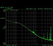
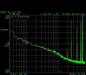
A common 3V open/100mA short 2x2" mono crystalline solar cell is illuminated by 4 high power white LEDs (total of 12.7V/350mA in series) at about 1/2" distance. The solar cell had measured about 70mA short current when exposed to sun, with the four LEDs the short current is only about 20mA (due to the non uniform illumination and mismatch between the cell sensitivity and the "cool white" LED emission spectra, "warm white" would be much more appropriated) but anyway much more than required to feed a ZXT Leach style preamp. Therefore, the internal resistance of the solar cell source is estimated to about 150ohm. Open voltage noise measurements are via a 60dB low noise (0.35nV/rtHz) instrumentation FET preamp (self made).
Without any filtering the open voltage noise is rather large and reaches about 2nV/rtHz at 50KHz and up. We can assume that the flat noise of the solar cell is essentially the internal source resistance thermal noise, which accounts of 1.5nV/rtHz out of the measured flat noise @50KHz.
However, @1KHz the unfiltered noise is about 76nV/rtHz, which I cannot explain on top of my head by anything but some sort of G-R noise (need to check the literature about noise in solar cells). The lower frequency noise is not 1/f, since it does not have the 10dB/decade slope (but close to 20dB/decade), it appears that solar cells have their particular LF noise mechanisms. Something that looks like to a "noise corner frequency" is around 25KHz!
Filtering the solar cell output solves the gross noise problem. A 1000uF/6.3V of the aluminum polymer very low ESR electrolytic capacitor filters out the noise, now the noise @1KHz is about 6nV/rtHz, not too shabby, but still needs careful consideration when targeting a deep sub nV/rtHz preamp with not much PSRR (if at all). The 50KHz flat noise is about the same as for the unfiltered example (2.5nV/rtHz) and the "noise corner frequency" is slightly lower, about 20KHz. The slope is now about 5dB/decade, which shows this is still no 1/f noise, but probably remnants of the original G-R noise.
Bottom line, although feeding a MC Leach type preamp using one or more photocells seems straightforward, it still needs lots of attention with filtering, to avoid power supply noise injection.
P.S. Yep, the first reference I found on line confirms the very G-R noise origin of an illuminated solar cell open voltage. It also confirms the rather high frequencies (for audio) where the G-R noise rises over the thermal noise (tens of KHz).
Attachments
Last edited:
Circa 1980, both Great Guru Baxandall and I looked at a lot of power devices (including some early ZTXs) for LoZ LN. He was doing MC RIAA for QUAD. We found some good ones but the killer was 1/f noise which needed a lot of selection.... almost every modern bipolar power device can be used as "low noise".
Then I found the Hitachi devices and stopped looking as they had guaranteed low rbb', high hfe & no 1/f noise.
Dunno about 'modern' power devices but I suppose ZTX 851/951 could be considered examples 🙂
It was this project that really crystallized my understanding of BJT noise and led to some interesting correspondence with GG Bax. 😀 I had just done the Calrec Mk4 Soundfield at 2G and as I had now done SOTA noise at both ends of the resistive spectrum, decided I would write a LN article as a guru. I sent the draft to GG Bax who gently but firmly, took me apart.
Last edited:
Circa 1980, both Great Guru Baxandall and I looked at a lot of power devices (including some early ZTXs) for LoZ LN. He was doing MC RIAA for QUAD. We found some good ones but the killer was 1/f noise which needed a lot of selection.
Those were not modern times, but Jurassic times. 99% of the consumer power devices of the time (excluding the military stuff) were of the 2N3055 triple diffused type. The japs did eventually develop processes (of IC complexity) driven by the video amplifier stages requirements; the low noise devices derived mostly from these processes (ion implanted, polysilicon emitter). This also explains why these devices are today extinct, no more market for such devices. The ZTX devices are one lucky shot, with their lows (in particular low Beta, the Hitachi devices had about the same under 2 ohm Rx, but Betas of 800-1000, leading to low current noise).
- Home
- Source & Line
- Analogue Source
- Richard Lee's Ultra low Noise MC Head Amp