What do they quote for rbb'? Do they detail their method?H&H measured it. It's in AoE V3.
Yes Horowitz and Hill detailed their measurement method for extracting rbb'; see section 8.12 which includes the circuit schematic on p.557. Better yet, one of the authors (Winfield Hill) wrote a post about it, right here on diyAudio: link. His post includes the following delightful remarks:
This is information I would have died for in years past, that's what motivated me, and now I can go forward on designs using all this grand data. DIY experimenters can too, if they get a copy of our book. 🙂
A pirate scan of pages 507 & 508 of TAOE v3 just arrived in my email. They sayBut seriously folks. ZTX 851/951 are about as close to perfect LN BJT devices as any I've encountered ... certainly the lowest rbb' I've ever seen. My estimate is 1R2 or less.
"at Ic = 10 mA a typical (average of six samples) pnp ZTX951 measured en=0.2nV/rt(Hz), compared with 0.21 nV/rt(Hz) for the ZTX851 npn complement (corresponding to rbb' values of 1.2R and 1.5R respectively)."
So da true gurus at TAOE v3 confirm da beach bum holding his wet finger in the wind at Cooktown extrapolating from other guru data .. particularly Wayne at proaudiodesign.com 😀
Incidentally, Eric Benjamin & I were planning a transformerless ribbon mike too with my circuit. It essentially gets any specified very LoZ noise performance with up to half the number of BJTs & half the current or less compared to any other circuit except a transformer thingy. But I was wary of running even that current near a STC/BBC/Coles ribbon directly.
Last edited:
There are some measurements here Ultra low noise amplifiers These don't get the same 1/f curve as H&H did but would tend to believe them more, but the general trend is the same. Interestingly the higher voltage ZTX853/953 comes in about the same, but does have slightly lower Cob if that is needed.
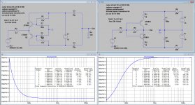
I have simmed both circuits below.JC’s circuit with single ZTX devices is siming at 340 pico Volt/rt Hz and 0.09% 20 k THD.
First is exactly nr 21 from your documentation, called JL and the other one is the single transistor John Curl called JL in the sim.
Gain for the JL circuit is 34.47, so I matched JC to exactly this same gain.
Noise for JL including the 4R3 input resistor is 340pV/rtHz.
When subtracting the noise from the 4R3, noise for the amp is 209pV/rtHz.
There are a few differences though, current supply is a bit higher at 2.78mA but distortion is notably lower at 0.005% (your doc says 0.07%)
With the same gain, JC has 439pV/rthz including the 4R3. Without the 4R3 it becomes 347pVrthz, or 4.4dB more as JL.
Distortion is 0.007%, or 3dB more as JL.
So our noise results are spot on the same !
But THD for both circuits differs more than a factor 10 in both cases, any idea why ?
Hans
Attachments
I would like to add to the above that RTI figures have to be regarded with some care, because the Carts serial resistance will of course add to the RTI noise.
When allowing 2dB extra noise added to the noise from the Carts serial resistance, maximum RTI should be 0.2nV/rtHz for a 4R3 cart.
When using a 10R cart, maximum RTI should be 0.3nV/rthz.
I wonder how many of us have Carts with such low serial resistances ?
Hans
When allowing 2dB extra noise added to the noise from the Carts serial resistance, maximum RTI should be 0.2nV/rtHz for a 4R3 cart.
When using a 10R cart, maximum RTI should be 0.3nV/rthz.
I wonder how many of us have Carts with such low serial resistances ?
Hans
BTW, where is this list of MM generators from George & Hans ?
I grovel at your feet Guru Polak 😱 Anyone doing this work demands the utmost respect so I beg forgiveness for dissing your worship of the false prophet JC.Cartridge dynamic behaviour If I have linked correctly this is the bulk of the information found.
______________________________________________________
Thanks for this Hans.Hans Polak said:I have simmed both circuits below.
First is exactly nr 21 from your documentation, called JL and the other one is the single transistor John Curl called JL in the sim.
Gain for the JL circuit is 34.47, so I matched JC to exactly this same gain.
Noise for JL including the 4R3 input resistor is 340pV/rtHz.
When subtracting the noise from the 4R3, noise for the amp is 209pV/rtHz.
There are a few differences though, current supply is a bit higher at 2.78mA but distortion is notably lower at 0.005% (your doc says 0.07%)
With the same gain, JC has 439pV/rthz including the 4R3. Without the 4R3 it becomes 347pVrthz, or 4.4dB more as JL.
Distortion is 0.007%, or 3dB more as JL.
So our noise results are spot on the same !
But THD for both circuits differs more than a factor 10 in both cases, any idea why ?
Your original post #100 circuits show wonky versions of a wonky Leach variant. But that isn't JC's 1977 patent which is a wonky Virtual Earth. The collector-base resistor is important. That's why THD isn't as bad as I expected.
We can certainly get the noise performace to match my circuit. Just get rid of the 10R emitter resistors. BTW, your C1,2 need to be 1000uF or response will be wonky. 100uF also makes it seem as though your noise improves at LF 🙂
Similarly but in an opposite fashion, C1,2 on my circuit should be 470uF.
If you do all this and run the same current, I expect both to have the same noise performance with the same cartridge. Not sure if THD will improve or get worse. It's very late here in Cooktown.
Standing back as far as I can, I think the factor that will prevent 'real life' production from emulating the sims in JC's will be the 1000uF caps. The differences in noise & THD are really moot except for 'my **** is bigger' issues 😀
No I can't explain the differences in THD between your sims & Bonsai but I'm too tired to think straight.
________________________________
Bonsai, once Hans has checked out my suggested improvement for JC, this might be the favoured powered version for VLN LoZ. Gotta get my finger out and do a full THD sweep with level.
Hans, can you post your *.ASC files? If you rename them *.TXT, diyaudio will allow them to be uploaded.
________________________________
BTW, if you are using the Diode Inc. SPICE models for noise analysis, you should make RB=1.2 & 1.5 for ZTX 951 & 851
Last edited:
I have simmed both circuits below.
First is exactly nr 21 from your documentation, called JL and the other one is the single transistor John Curl called JL in the sim.
Gain for the JL circuit is 34.47, so I matched JC to exactly this same gain.
Noise for JL including the 4R3 input resistor is 340pV/rtHz.
When subtracting the noise from the 4R3, noise for the amp is 209pV/rtHz.
There are a few differences though, current supply is a bit higher at 2.78mA but distortion is notably lower at 0.005% (your doc says 0.07%)
With the same gain, JC has 439pV/rthz including the 4R3. Without the 4R3 it becomes 347pVrthz, or 4.4dB more as JL.
Distortion is 0.007%, or 3dB more as JL.
So our noise results are spot on the same !
But THD for both circuits differs more than a factor 10 in both cases, any idea why ?
Hans
I probably have not turned compression off Hans - I will redo and check. Your distortion #'s look good ans I believe probably reflect reality a bit better than mine. Thanks for confirming the #'s BTW.
Last edited:
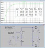
I should have used 1mF instead of 100uF caps, an error that fortunately had no effect on noise and THD.We can certainly get the noise performace to match my circuit. Just get rid of the 10R emitter resistors. BTW, your C1,2 need to be 1000uF or response will be wonky. 100uF also makes it seem as though your noise improves at LF 🙂
When removing the 10R resistors, but still with the Diode spice model, with gain again adjusted to 34.47, noise at 1Khz becomes 317pV/rtHz with the 4R3 and 169 pV/rtHz without.
THD goes even to 0.005%.
So indeed, both topologies have roughly the same performance.
See sim below.
When changing both RB values to the numbers you supplied, noise at 1Khz increases from 317 to 335 pV/rthz, or just 0.5 dB.Hans, can you post your *.ASC files? If you rename them *.TXT, diyaudio will allow them to be uploaded.
________________________________
BTW, if you are using the Diode Inc. SPICE models for noise analysis, you should make RB=1.2 & 1.5 for ZTX 951 & 851
Attachments
Last edited:

When changing both RB values to the numbers you supplied, noise at 1Khz increases from 317 to 335 pV/rthz, or just 0.5 dB.
Very optimistic numbers. What your simulation is telling you is that noise is essentially the 4.3ohm resistor noise, plus a minuscule component due to the base current noise, so basically your transistor models are voltage noiseless and only the base current shot noise is considered. At these noise levels, you would also need to account in the noise model for RE, the flicker noise and perhaps the popcorn noise (~1/f^2), both current noise components that are zero by default in the Spice default bipolar model. Parameters for these are unknown and anyway not guaranteed, since the ZTX are not intended for low noise applications.
The ZTX are accidentally good low noise devices, but I would not get very excited about; almost every modern bipolar power device can be used as "low noise". I recall measuring the RB for the 8A/150V in TO220 MJE15030/15031 and got around 10ohm while the TO3 plastic MJL4281 (15A/350V) had around 2.5ohm. The beauty of the ZXTs is in the friendly TO92 package 😀.
Only solution ultimately is to built it and test is wrt these other noise sources - no idea how you would model that or even if it is possible.
Why don't you just plot Vinoise Hans?
It’s just a habbit to document the gain at the same time.
That’s why I always look at the output.
Hans
The Rb is under 2 ohms for the ZTX851 which is good enough until I finally score a Nagatron ribbon cartridge (note this is unlikely to occur given how rare they are) at 0.04mV. Based on measurements of the balanced unit Wayne Kirkwood designed (and I'm planning to build) it may not win a willy waving award but will do the job very nicely and cause suitable offense to golden ear types due to topology and nasty 8 legs. Hans worked out it was a gnats whisker over 0.5nV/rtHz (not sure if weighted or not).
Once I have a working reference I can do Richards Altoids special for the willy waving rights 🙂
Once I have a working reference I can do Richards Altoids special for the willy waving rights 🙂
One more for the pile 😀
10% on Vbe, that's 10X in current. I don't know how you missed the version of this with massively paralleled JFET's, there have been several presented here. JFET's don't need ballast resistors to share current and at least you can couple the input with a decent film cap..
Last edited:
You are most likely too pessimistic in this case.Very optimistic numbers. What your simulation is telling you is that noise is essentially the 4.3ohm resistor noise, plus a minuscule component due to the base current noise, so basically your transistor models are voltage noiseless and only the base current shot noise is considered. At these noise levels, you would also need to account in the noise model for RE, the flicker noise and perhaps the popcorn noise (~1/f^2), both current noise components that are zero by default in the Spice default bipolar model. Parameters for these are unknown and anyway not guaranteed, since the ZTX are not intended for low noise applications.
The simmed 200pV/rtHz RTI is equivalent to 2R4 or 1R7 per transistor with the standard Diode Spice model.
Is this an unrealistic value at 1Khz, I don't get that feeling.
Look at the link I gave here: Richard Lee's Ultra low Noise MC Head Amp
The simulated noise value was even 0.5dB higher as the measured noise value.
That's quite o.k. for me to give enough confidence in the Spice model.
Hans
10% on Vbe, that's 10X in current. I don't know how you missed the version of this with massively paralleled JFET's, there have been several presented here. JFET's don't need ballast resistors to share current and at least you can couple the input with a decent film cap..
ok - that's true on the Ic - thanks for pointing it out. Obviously it would require tighter matching or some sacrifice in noise for ballasting.
re the cart coupling, I have a version in the pipeline that servo's the dVbe across the input device and the bias reference, so you could in theory direct couple the cart, but would still need to decouple the ref side to ground with a large cap for noise purposes (surprised you are worried about caps BTW . . . )
I've seen the JFET thing, played with it and wrote it up in my RIAA article way back - a development of Denis Collin's 'LP797' idea. I know Syn08 also ran with it as well. I'll resurrect that in due course for the compendium.
...at 0.04mV.
AudioNote cart territory.....
Anyway many thanks to all contributing here, it's a fine thread with some excellent links, I'm learning a lot!🙂
- Home
- Source & Line
- Analogue Source
- Richard Lee's Ultra low Noise MC Head Amp