One thing I wold appreciate you to explain is why I'm getting a tenths od-f dB on the right and hundredths of dBs on yours. Why is the scale changing?
R9 is 1 milliohm instead of 1 megohm in your simulation. As Spice is not case sensitive, in Spice syntax, 1 megohm is 1 meg.
The supply pins of the extra op-amp appear to be unconnected.
The only benefit compared to Hans's version is a reduction of the noise. Otherwise it is supposed to do practically the same as the circuit from post #1.
The only benefit compared to Hans's version is a reduction of the noise. Otherwise it is supposed to do practically the same as the circuit from post #1.
I've also seen it used along with an Anti-RIAA Laplace transform, e.g. Laplace=1/((1+318e-6*s)/((1+75e-6*s)*(1+3180e-6*s))) inserted into Value field of the VDVS, to take the place of the Anti-RIAA resistor /capacitor network.
(...)
Slightly off-topic but I'd be interested in the pros and cons of the Laplace vs the resistor/capacitor approach.
The advantages I can think of for the resistor/capacitor approach are that you can also use them in simulators or simulations that don't support Laplace expressions and that you can actually build such an inverse RIAA network and 1:1 compare measurements with simulations. I'm not sure if LTSpice only supports Laplace expressions for small-signal (.ac) analyses or also for transient analyses.
The approach with the Laplace expression is more accurate and doesn't generate any noise.
Another opamp which might be great to replace the LT1792 is the OPA827.
Pity it's awfully expensive: >$15 each.
The main differences between the OPA827 and OPA1652, apart from the OPA1652 being a dual op-amp, are that the OPA827 has a very low offset for a FET op-amp, it has a higher slew rate and it has a settling time specification. Those are major advantages when you want to use them in high-speed measuring equipment, but shouldn't matter much for a RIAA amplifier (assuming you will block the amplified offset somewhere).
@Carlmart
For your information, with the Cart connected S/N A-weighted ref 5mv@1Khz is resp:
80dB-A with 47K and the 75usec filter between stage 1 and stage 2
73dB-A with a Cart termination of 4K78
79dB-A with the "cooled" version as the type that MvdG has shown.
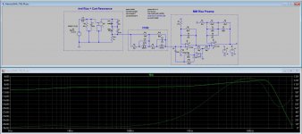
FR with cooling is as before without, just as shown in the image below.
Mind you that 73dB-A with Cart connected is still excellent, so there's no obvious need for the extra complexity.
Hans
For your information, with the Cart connected S/N A-weighted ref 5mv@1Khz is resp:
80dB-A with 47K and the 75usec filter between stage 1 and stage 2
73dB-A with a Cart termination of 4K78
79dB-A with the "cooled" version as the type that MvdG has shown.
FR with cooling is as before without, just as shown in the image below.
Mind you that 73dB-A with Cart connected is still excellent, so there's no obvious need for the extra complexity.
Hans
Attachments
A Shure V15-III produces only 3.5 mV at 5 cm/s, so the A-weighted signal to noise ratio related to 5 cm/s is only about 69.9 dB, close to the 69.57 dB(A) I calculated here: https://www.diyaudio.com/forums/ana...-preamps-versus-real-loads-2.html#post6377134
Mind you, I only took the termination resistor thermal noise into account. When you transform the 4.2 nV/sqrt(Hz) of the first op-amp backwards through the 4.78 kohm termination resistor of the circuit of post #1, you get a noise current term of 0.8787 pA/sqrt(Hz). When you add that in power to the 1.8404 pA/sqrt(Hz) of the termination resistor itself (at 20 degrees C), it should aggravate the noise by another 0.89 dB. So then the discrepancy between your simulation and my calculation is at least 1.22 dB rather than 0.33 dB.
All of it is only important for Merlin anyway, as Carlos has no Shure V15-III.
Last edited:
By the way, it would be interesting to see what the cooled and the hot version do with dirt cheap TL071 op-amps. I wouldn't be surprised if the cooled version with TL071s had a similar noise level as the hot version with LT1792s.
@Carlmart
For your information, with the Cart connected S/N A-weighted ref 5mv@1Khz is resp:
80dB-A with 47K and the 75usec filter between stage 1 and stage 2
73dB-A with a Cart termination of 4K78
79dB-A with the "cooled" version as the type that MvdG has shown.
FR with cooling is as before without, just as shown in the image below.
Mind you that 73dB-A with Cart connected is still excellent, so there's no obvious need for the extra complexity.
Which was the 80dB-A version with 47K you mention? The one I did got me a big hump going up 9dB, from 1KHz to 17KHz. To get flatness I need 4K78 load. Is there other option for a straight FR?
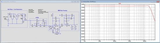
Simulated the Marcel "cooled" version you did, and it did get me a flat FR up to 17KHz.
I did some small changes in your schematic, going to the more standard values of 57K and 200p, instead of the ones you put, and replace the 4.7u with a film 470n. I hope that's alright, for nothing seemed to change in FR.
If the values have to be the ones you put, please do tell me why.
Attachments
By the way, it would be interesting to see what the cooled and the hot version do with dirt cheap TL071 op-amps. I wouldn't be surprised if the cooled version with TL071s had a similar noise level as the hot version with LT1792s.
If I had TL071 models to use on my simulation I would certainly try them, and see what changes. Noise might probably be affected.
I made a slight change in the layout by replacing the 2n5 cap over the first stage to behind R10, now being 6nF.
This has several advantages:
1) you can freely change the gain of the first amp without worrying about changing the parallel cap.
2) when using the "cooled" version, the 207pF cap par to the 57K4 resistor can be discarded, making it a much easier to find the right resistance value when changing to another Cart.
I rounded the S/N figures to integers, but in fact there is only 0.5dB between the hot version and the cooled version.
I have no TL071 model but with 18nV/rtHz @ 1Khz I think the LT1792 with 4.2nV/rtHz is almost as good as it can be.
The OPA164x could be an alternative with single, dual and quadruple versions.
And regarding a S/N of 73dB-A, keep in mind that some of the most expensive and well regarded Riaa preamps (Stereophile) have lower noise figures, such as the $60,000,- Vitus with 62.8dB-A and the $36.000,- Boulder 2008 with even 58dB-A.
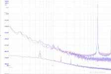
As a reference see here the noise from a 75dB-A preamp L/R in the lower trace against the surface noise of a new Feickert test LP with resp. an unmodulated track versus a track with a 1Khz test tone at 5cm/sec.
Where they are closest, there is still more than 15dB between the surface noise and the preamp noise, showing that even 66dB-A will only increase the surface noise by an almost insignificant 1dB.
The Boulder 208, producing comparable noise as the surface noise, will increase noise by 3dB, under the assumption that Stereophile measured correctly.
Maybe adding the noise was part of the magic of the Boulder, who knows.
Hans
This has several advantages:
1) you can freely change the gain of the first amp without worrying about changing the parallel cap.
2) when using the "cooled" version, the 207pF cap par to the 57K4 resistor can be discarded, making it a much easier to find the right resistance value when changing to another Cart.
I rounded the S/N figures to integers, but in fact there is only 0.5dB between the hot version and the cooled version.
I have no TL071 model but with 18nV/rtHz @ 1Khz I think the LT1792 with 4.2nV/rtHz is almost as good as it can be.
The OPA164x could be an alternative with single, dual and quadruple versions.
And regarding a S/N of 73dB-A, keep in mind that some of the most expensive and well regarded Riaa preamps (Stereophile) have lower noise figures, such as the $60,000,- Vitus with 62.8dB-A and the $36.000,- Boulder 2008 with even 58dB-A.
As a reference see here the noise from a 75dB-A preamp L/R in the lower trace against the surface noise of a new Feickert test LP with resp. an unmodulated track versus a track with a 1Khz test tone at 5cm/sec.
Where they are closest, there is still more than 15dB between the surface noise and the preamp noise, showing that even 66dB-A will only increase the surface noise by an almost insignificant 1dB.
The Boulder 208, producing comparable noise as the surface noise, will increase noise by 3dB, under the assumption that Stereophile measured correctly.
Maybe adding the noise was part of the magic of the Boulder, who knows.
Hans
Attachments
@Carlmart,
Do you have the model of your Cart, than I can model it to your specific situation.
Hans
Do you have the model of your Cart, than I can model it to your specific situation.
Hans
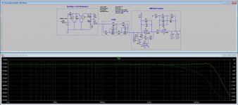
That was the version without the cooling, with a 47K Cart termination and with the 34.4nF cap behind R10.Which was the 80dB-A version with 47K you mention?
This is the usual bread and butter version.
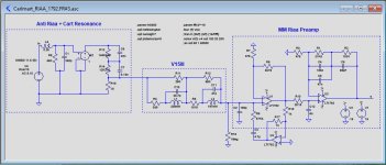
You have placed the 10K feedback resistor on the wrong place, it should be connected to the output of the amp.I did some small changes in your schematic, going to the more standard values of 57K and 200p, instead of the ones you put, and replace the 4.7u with a film 470n. I hope that's alright, for nothing seemed to change in FR.
Hans
I rounded the S/N figures to integers, but in fact there is only 0.5dB between the hot version and the cooled version.
I don't understand what you mean here. The 6 dB difference from post #46 can't possibly be due to rounding to integer numbers.
I referred to the 80dB-A "as usual" 47K version and the cooled 79dB-A version, that are in fact only 0.5dB apart.
Hans
Hans
I have no TL071 model but with 18nV/rtHz @ 1Khz I think the LT1792 with 4.2nV/rtHz is almost as good as it can be.
Connect a 9.24 kohm resistor in series with each input of the LT1792 model and you have roughly the noise of a TL071/TL072/TL074.
LT1792: 4.74 to 8.96 euro at Mouser (single op-amp)
TL071: 0.339 to 0.525 euro at Mouser (single op-amp)
TL074: 0.465 to 2.24 euro at Mouser (four op-amps)
OPA1656: 2.31 to 2.50 euro at Mouser (two op-amps)
TL074 is certainly interesting if you want to keep it cheap.
Try this as a .sub. I seem to remember getting this from TI's web resources and doing the recommended tweaks to use it within LTSPICE.I have no TL071 model ...
View attachment TL072.txt
I promised to write something about DC feedback loops. When you look at the explanations people give for perceived differences in sound quality between different types of DC blocking capacitors, those explanations/hypotheses fall into three categories:
1. Smeared out time response due to dielectric absorption
2. Capacitor distortion
3. Self-delusion (or whatever may be the correct psychological term) by audiophiles who do uncontrolled listening tests
One can argue that any kind of high-pass filter smears out the signal, and an ideal coupling capacitor and bias resistor also form a high-pass filter. Therefore, it isn't clear why smearing out due to dielectric absorption would be worse than the smearing out you already get with ideal components. One can also argue that the distortion of all but the very worst types of capacitors (ceramic class 2 and tantalum) is almost always negligible compared to other sources of distortion.
In any case, the dielectrics with least dielectric absorption are usually also the dielectrics with least distortion and the dielectrics that audiophiles tend to find most acceptable. Instead of figuring out what causes capacitor sound, one can therefore just choose a capacitor with a dielectric that performs well according to all three hypotheses, such as a polypropylene capacitor. The disadvantage of this approach is that capacitors with large values (more than a few uF) become quite large and expensive.
I think DC bias loops have two advantages:
A. They sometimes allow you to use smaller capacitance values than you would otherwise need. You can then use a capacitor with a good dielectric that is still cheap, rather than an expensive large one. (If dielectric absorption matters at all, the dielectric absorption of the capacitors in the DC bias loop is just as critical as that of ordinary DC blocking capacitors.)
B. With DC blocking capacitors, you always end up with a cascade of first-order high-pass filters, each blocking capacitor and bias resistor forming one first-order high-pass section. With DC bias loops or a combination of DC blocking and bias loops, you can also make other filter types, second-order Butterworth for example.
@Carlmart,
Do you have the model of your Cart, than I can model it to your specific situation.
No, I don't .
First I will have to exactly identify my model, which I think is Grado MR8.
Will find out soon, I think, but not so sure about the model.
- Home
- Source & Line
- Analogue Source
- RIAA preamps versus real loads