Perhaps some of you would find this of interest.
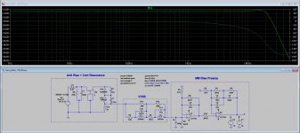
It's an early (simplified) RIAA opamp design which includes models for cartridge/pickup arm behaviors etc. based on measurements of a specific cartridge- the Miyajima Madake.
The full preamp, somewhat modified, extended and improved, is on a thread in this forum.
it also includes a Laplace RIAA model, A weighting measurement networks etc.
Can you put URL for the full preamp thread or the name of the thread? The characters here are impossible to read.
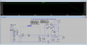
Would anyone be kind and explain to me why loading that complex antiresonance antiriaa + cart model as the manufacturer recommended , the resonance at 10.8khz is still there?
This one has no resonance hump.
Attachments
Can you put URL for the full preamp thread or the name of the thread? The characters here are impossible to read.
Ultra high spec. opamp MC/MM phono, warp "elliptic" filter, line, headphone amps.
That thread does not include the cartridge etc. modelling.
If anyone is interested I will post them in more visible forms.
Ultra high spec. opamp MC/MM phono, warp "elliptic" filter, line, headphone amps.
That thread does not include the cartridge etc. modelling.
If anyone is interested I will post them in more visible forms.
Quite complicated circuit!
One thing I found interesting is adding a DC servo on the first MM stage (U7), as there it might not interact with the RIAA eq. Don't you think, Marcel?
Could one be added to the circuit above with good results?
Yes, the circuit is quite complex. Each section has a part to play, perhaps sometimes not as obviously as it might appear.
If anyone is interested I would be happy to perform a small "design review" over a series of posts explaining the partitioning and location of the pole-zero constellation, the rationale for the gain distributions and choice of opamps, the effect of the choices on distortion, RIAA accuracy, power supply rejection, and overload characteristics. It would also include the post power supply LCRC filtering and the design elements of the DC feedback loop and how it is incorporated into the RIAA.
For example the design is NOT simply a fixed gain block followed by an RIAA curve stage. the interstage filter is part of the DC feedback stage and part of the extended RIAA characteristic etc.
I would also include the cartridge arm modelling, the A weighting measurement network and other minutiae.
It could also include details of the incorporated first order warp filter design that replaces a conventional "rumble filter".
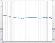
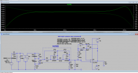
Below is the measured result from one RIAA channel of a preamp built with non-selected off the shelf components.
This is a typical curve for the several boards that I have constructed and measured, and they deviate very little from it.
The measurements are made with the RME ADI-2PRO FS R plus REW. The gain was compared against an ideal RIAA gain template in a spread sheet and "interpolated" between points- which results in the odd small dips. The HF ripple is due to the converter transfer functions. The RME box DAC is used to source the signal, and the ADC is used to measure it
If anyone is interested I would be happy to perform a small "design review" over a series of posts explaining the partitioning and location of the pole-zero constellation, the rationale for the gain distributions and choice of opamps, the effect of the choices on distortion, RIAA accuracy, power supply rejection, and overload characteristics. It would also include the post power supply LCRC filtering and the design elements of the DC feedback loop and how it is incorporated into the RIAA.
For example the design is NOT simply a fixed gain block followed by an RIAA curve stage. the interstage filter is part of the DC feedback stage and part of the extended RIAA characteristic etc.
I would also include the cartridge arm modelling, the A weighting measurement network and other minutiae.
It could also include details of the incorporated first order warp filter design that replaces a conventional "rumble filter".
Below is the measured result from one RIAA channel of a preamp built with non-selected off the shelf components.
This is a typical curve for the several boards that I have constructed and measured, and they deviate very little from it.
The measurements are made with the RME ADI-2PRO FS R plus REW. The gain was compared against an ideal RIAA gain template in a spread sheet and "interpolated" between points- which results in the odd small dips. The HF ripple is due to the converter transfer functions. The RME box DAC is used to source the signal, and the ADC is used to measure it
Attachments
Last edited:
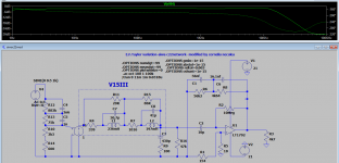
I have no idea whay the anti riaa network is said to have cart antiresonance parameters when actually it seems that the loading and topology itself does that while the normal manufacturer's recommended loding doesn't change the resonance hump, but anyway, the overall results look very good.This one has no resonance hump.
The only thing i don't see is how that kind of loading and antiriaa + cart antiresonance is needed .I can''t see Hans cart model advantage either.Here's the schematic and FR curve.
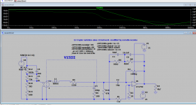
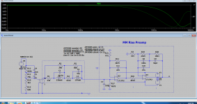
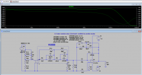
If i use the simplest simulation model i gave you a while ago, the simple 600mH series with 1350ohm model instead of that very complex model and Patrick Turner's anti riaa on a normal preamp like mine i get 0.8db of resonance at 10.8khz with normal 47k//430pf loading and normal equalization network...which is very close to your complex models.
If i'm using the same simple antiriaa and simplest shure model with Hans loading and preamp i get worst possible results over 100hz.
Not commenting on the noise specs which are brilliant in your schematics, but the FR are really unconvincing for me because the normal antiriaa which was built and measured by me years ago and found to be extremely linear and simplest Shure model plus normal loading or more advanced Hans model give almost exact FR response .
You have all combinations explored and their FR graphs below .
Attachments
-
 Turnerantiriaa, normal shure, normal loading EFTpreamp100meg.png63.7 KB · Views: 124
 -
 Turner antiriaa, hans cart, efpreamp100megHz.png66.7 KB · Views: 117
 -
 Patrickantiriaa-Hans cartmodel-EFtaylor preamp.png60.4 KB · Views: 142
 -
 turner antiriaa, hans cart, hans preamp.png78.7 KB · Views: 142
 -
 normalantiriaa-carlmart model-hans loading.png52.3 KB · Views: 145
 -
 eftaylor Hans loading.png52.9 KB · Views: 151
 -
 eftaylor normal loading.png62.9 KB · Views: 157
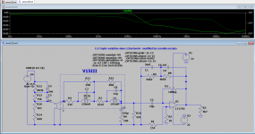
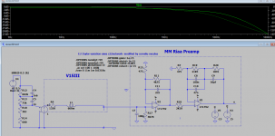
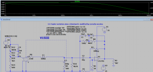
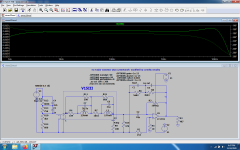
Sorry, Hans model moved that small resonance hump around 15 khz yet the whole antiriaa, antiresonance, cart model, loading and phono preamp together get you acceptable linear response...yet if i apply Hans antiriaa, antiresonance and Hans Shure model with a normal loading to a normal preamp(and you have both EF taylor and non efTaylor) i get a hump and quite nonlinear response over 10 khz , just more linear than the simplest Shure model with Turner antiriaa. The only real problem is that Turner antiriaa measures perfectly and it was chosen also by Texas instruments in their application notes.Not sure of the original provenience of that antiriaa network, but that is simply perfect in real life.
If Hans antiriaa+ antiresonance+ advanced Shure model can only give you a fairly linear response on a highly modified preamp and unnatural loading, but cannot give you a normal response with a normal loading and normal preamp, then what do you expect from the real thing on a normal preamp ?
Believe me, i hear no weird resonances on my shure v15 type 3 on none of the 10 preamps i tried in the last years nor on other cheaper shure, phillips ... carts .
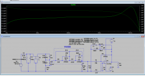
I still consider Hans cart model to be better than the simple LR model i gave you, but i don't find to be OK to modify the antiriaa network in order to give you the right FR on your preamps while a very linear anti-riaa network in real life with your same shure model on a normal preamp and loading to give non linear response.The antiriaa filter needs to be an inverse reflection of the riaa network not of the cart and its loading unless we're pretending that the whole industry used the wrong riaa network for 6 decades and that shure v15type 3 cart is the only cart ...
If Hans antiriaa+ antiresonance+ advanced Shure model can only give you a fairly linear response on a highly modified preamp and unnatural loading, but cannot give you a normal response with a normal loading and normal preamp, then what do you expect from the real thing on a normal preamp ?
Believe me, i hear no weird resonances on my shure v15 type 3 on none of the 10 preamps i tried in the last years nor on other cheaper shure, phillips ... carts .
I still consider Hans cart model to be better than the simple LR model i gave you, but i don't find to be OK to modify the antiriaa network in order to give you the right FR on your preamps while a very linear anti-riaa network in real life with your same shure model on a normal preamp and loading to give non linear response.The antiriaa filter needs to be an inverse reflection of the riaa network not of the cart and its loading unless we're pretending that the whole industry used the wrong riaa network for 6 decades and that shure v15type 3 cart is the only cart ...
Attachments
-
 Turner Riaa, Hans cart, normal loading normal preamp.png59 KB · Views: 126
 -
 Turner antiriaa, Hans cart, normalloading normal amp.png144.7 KB · Views: 109
 -
 hans cartm hans antiriaa, hans model, normal preamp.png58.4 KB · Views: 103
 -
 NON-taylornormalpreamp-hans antiriaa, cart and normal loading.png66 KB · Views: 123
I'm responding quite a bit later to your comments. At last, after these many years, I'm about to assemble two MM RIAA preamps: one passive active, one all passive.Carl: If you have a Grado that changes the reference for you. Grados are insanely low impedance for an MM so many of the problems that can occur with loading on other MMs it is immune to. In return you get a whole new set of problems 🙂.
The first will follow Erno Borbely recipe, and the second Walt Jung suggested values.
I have two RIAA kits I bought from Aliexpress, one for each type. Their parts layout for their original circuit needs just a few mods, mainly in values, to get the preamps I simulated.
Can you tell which are the problems I might have with the Grado Reference? You said they are lower impedance, so which load values should I try?
Pity I won't be able to get a test LP, which would be the right way to proceed.
Regards,
Carlos
- Home
- Source & Line
- Analogue Source
- RIAA preamps versus real loads