I've been using this RIAA circuit for many years with good results. Curious what you think of it. I tend not to need a lot of gain. Since I bought a lot of LME49710 opamps, that's what I use.
I have no access to LTSpice at the moment so I haven't a clue what your circuit looks like, but the noise current of an LME49710 is a bit high for moving magnet.
Very interesting I own a Shure V15-III original, please could you post the full schematic, thanks in advance?
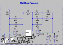
After removing some leftovers that don't seem to be useful anymore and correcting the two wrong component values, you end up with the attached schematic. 57.6 kohm is an E96 standard value, you can get 206 pF by connecting 150 pF in parallel with 56 pF. The extra op-amp could for example be an OPA134 or the same type of FET op-amp as used in the rest of the circuit. Details like power supply decoupling are obviously still missing.
Attachments
I did an A <> B test with several LP's ( Fleetwood Mac dire straights M Jackson) and the CD version of the same. I then "adjusted" the RIAA components until the A<>B test had the same response flavour.
The resulting preamp is NOT RIAA compliant, but the sound is stunning.
you will find that Left and Right need slightly different EQ to sound correct.
The resulting preamp is NOT RIAA compliant, but the sound is stunning.
you will find that Left and Right need slightly different EQ to sound correct.
After removing some leftovers that don't seem to be useful anymore and correcting the two wrong component values, you end up with the attached schematic. 57.6 kohm is an E96 standard value, you can get 206 pF by connecting 150 pF in parallel with 56 pF. The extra op-amp could for example be an OPA134 or the same type of FET op-amp as used in the rest of the circuit. Details like power supply decoupling are obviously still missing.
Thanks.
Let me try to find the specs for this Grado, which apparently was quite different from other Grados. I think it was type MR8, but I am not sure.
If you can dig up information about the resistance, inductance, recommended load and frequency response with the recommended load, we can try to do for the Grado what Hans did for the Shure.
Also I wonder if the DC offset results will be as low as the sim shows, or if a simple output cap would block it with minimum audible cap distortion.
You were the one that warned me, very properly, against what a DC servo might cause on a RIAA preamp. Borbely did use them, but he knew what he was doing. The Gary Galo mod to the LT/Adcom preamp also used a servo, but they also knew what they were doing. I do not.
OTOS, do you think is valid or useful to add a DC servo to a high offset (>30mV?) preamp and listen to how it affects the sound?
There will be a substantial offset at the output, worst case about 500 times the maximum offset of the first op-amp plus 45 times the maximum offset of the second op-amp (as specified in their datasheets). The easiest way to block it is with a DC blocking capacitor.
I'll get back to DC loops later.
After removing some leftovers that don't seem to be useful anymore and correcting the two wrong component values, you end up with the attached schematic. 57.6 kohm is an E96 standard value, you can get 206 pF by connecting 150 pF in parallel with 56 pF. The extra op-amp could for example be an OPA134 or the same type of FET op-amp as used in the rest of the circuit. Details like power supply decoupling are obviously still missing.
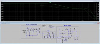
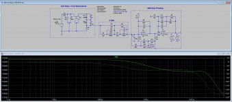
Marcel, you can't imagine how much appreciate what you are doing, even if I don't quite understand what it is. Hereby I enclosed the simulations of both designs you did, hopefully no having read some part spec wrongly.
The problem seems to be the frequency response I'm getting, which stopped being flat as it was before.
Can you explain a little more of what you were trying to correct and why?
Please remember that I won't be using a Shure V15, but many people are, so getting to a flat FR with it should continue to be a valid task.
Enclosed, just for comparison, is the original Hans design.
One thing I wold appreciate you to explain is why I'm getting a tenths od-f dB on the right and hundredths of dBs on yours. Why is the scale changing?
Attachments
LT1792 is obsolete and I don't want to buy to U.S.A. there is some equivalent or European seller?
Where did you get that information?
https://www.analog.com/en/products/lt1792.html
Product Lifecycle: Production
Neither is it considered obsolete in Mouser.
There's a dual JFET opamp, can't remember the name now, that has similar specs, though realistically probably not as good.
https://www.analog.com/en/products/lt1792.html
Product Lifecycle: Production
Neither is it considered obsolete in Mouser.
There's a dual JFET opamp, can't remember the name now, that has similar specs, though realistically probably not as good.
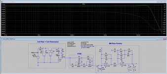
It's a voltage dependent voltage source (VDVS).Sorry my ignorance: What's E2 in the Anti RIAA+Cart resonance module?
It is used in this particular case to isolate the voltage source and the cart mechanical resonance from the anti-RIAA resistor/capacitor network.
I've also seen it used along with an Anti-RIAA Laplace transform, e.g. Laplace=1/((1+318e-6*s)/((1+75e-6*s)*(1+3180e-6*s))) inserted into Value field of the VDVS, to take the place of the Anti-RIAA resistor /capacitor network.
I'm not a huge expert in any version of SPICE and if I've got it wrong someone will soon correct me.
Slightly off-topic but I'd be interested in the pros and cons of the Laplace vs the resistor/capacitor approach.
Last edited:
I think it's the OPA1652.
Muito obrigado Carlos, this is avaliable at RS & Farnell.
It's a voltage dependent voltage source (VDVS).
It is used in this particular case to isolate the voltage source and the cart mechanical resonance from the anti-RIAA resistor/capacitor network.
I've also seen it used along with an Anti-RIAA Laplace transform, e.g. Laplace=1/((1+318e-6*s)/((1+75e-6*s)*(1+3180e-6*s))) inserted into Value field of the VDVS, to take the place of the Anti-RIAA resistor /capacitor network.
I'm not a huge expert in any version of SPICE and if I've got it wrong someone will soon correct me.
Slightly off-topic but I'd be interested in the pros and cons of the Laplace vs the resistor/capacitor approach.
Thanks George.
Another opamp which might be great to replace the LT1792 is the OPA827.
Pity it's awfully expensive: >$15 each.
Does it work or improve anything to parallel a dual opamp, like the OPA1652?
Pity it's awfully expensive: >$15 each.
Does it work or improve anything to parallel a dual opamp, like the OPA1652?
This one seems to answer my question on paralleling, and suggesting the right way to do it.
https://e2e.ti.com/blogs_/archives/b/thesignal/archive/2013/03/26/paralleling-op-amps-is-it-possible
But looking at the arrangement 2, I think it would be quite complicated to parallel two opamps on the second stage.
https://e2e.ti.com/blogs_/archives/b/thesignal/archive/2013/03/26/paralleling-op-amps-is-it-possible
But looking at the arrangement 2, I think it would be quite complicated to parallel two opamps on the second stage.
The alternative, in case the LT1792 stops being made, and the OPA1652 is still available , might be to design a different pcb, making it almost mandatory to be double sided,
or to use just one of the opamps inside the dual.
That might not be easy either, because power pins, as well as inputs and outputs are different on singles and duals.
or to use just one of the opamps inside the dual.
That might not be easy either, because power pins, as well as inputs and outputs are different on singles and duals.
- Home
- Source & Line
- Analogue Source
- RIAA preamps versus real loads